Page 3 - Table of Contents; Title; Battery Saver
i Table of Contents Title Page Introduction .................................................................................................................... 1 Contacting Fluke ............................................................................................................ 1 Safety In...
Page 4 - Users Manual; ii
1507/1503 Users Manual ii Testing the Batteries ...................................................................................................... 18 Testing the Fuse ............................................................................................................ 19 Replacing the Bat...
Page 5 - Introduction; Earth-Bond Resistance; Contacting Fluke; To register your product, visit
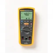
1 Introduction The Fluke model 1507 and model 1503 are battery-powered insulation testers (the Tester). Although this manual describes the operation of both Models 1507 and 1503, all illustrations and examples assume use of model 1507. These Testers meet IEC 61010 standards. The IEC 61010-2-030 stan...
Page 6 - Safety Information; identifies conditions and
1507/1503 Users Manual 2 Safety Information Use the Tester only as specified in this manual. Otherwise, the protection provided by the Tester may be impaired. See Table 1 for a list of symbols used on the Tester and in this manual. A Warning identifies conditions and procedures that are dangerous to...
Page 7 - from short circuits.
Insulation Testers Safety Information 3 • Use Product-approved measurement category (CAT), voltage, and amperage rated accessories (probes, test leads, and adapters) for all measurements. • Do not exceed the Measurement Category (CAT) rating of the lowest rated individual component of a Product, pro...
Page 8 - Symbol
1507/1503 Users Manual 4 Table 1. Symbols Symbol Description Symbol Description W WARNING. RISK OF DANGER. Earth X WARNING. HAZARDOUS VOLTAGE. Risk of electric shock. Fuse Consult user documentation. T Double Insulated Battery 6 WARNING. Do not use in distribution systems with voltages >6...
Page 9 - Unsafe Voltage; V in resistance, or a voltage overload; Figure 1. Rotary Switch
Insulation Testers Unsafe Voltage 5 Unsafe Voltage To alert you to the presence of a potentially hazardous voltage, when the Tester detects a voltage ≥ 30 V in insulation test, ≥ 2 V in resistance, or a voltage overload ( ), the symbol is displayed. Battery Saver (Sleep Mode) The Tester enter...
Page 10 - Table 2. Rotary Switch Selections; OFF; Buttons and Indicators; Figure 2. Buttons and Indicators
1507/1503 Users Manual 6 Table 2. Rotary Switch Selections Switch Position Measurement Function OFF Turn off the Tester. AC or DC voltage from 0.1 V to 600.0 V. Ohms from 0.01 Ω to 20.00 k Ω . 250V 100V 50V Ohms from 0.01 M Ω to 10.0 G Ω for the Model 1507 and 0.01 to 2000 M Ω for the Model ...
Page 11 - Table 3. Buttons and Indicators
Insulation Testers Buttons and Indicators 7 Table 3. Buttons and Indicators Button/ Indicator Description Press the blue button to select alternate measurement functions. Press to configure the Tester for a polarization index or dielectric absorption ratio test. The test will start when you pres...
Page 12 - Understanding the Display; Figure 3. Display Indicators; Minus or greater than symbols; XW; Warning
1507/1503 Users Manual 8 Understanding the Display Display indicators are shown in Figure 3 and described in Table 4. Error messages that may appear on the display are described in Table 5. bbw01f.emf Figure 3. Display Indicators Table 4. Display Indicators Indicator Description Indicates an insul...
Page 13 - Indicator; Table 5. Error Messages
Insulation Testers Understanding the Display 9 Table 4 Display Indicators (cont.) Indicator Description Polarization index or dielectric absorption ratio test is selected. ZERO Ohms lead zero is active. VAC, VDC, Ω , k Ω , M Ω , G Ω Measurement units Primary display VDC Volts Seconda...
Page 14 - Input Terminals; Input terminal for resistance measurement.
1507/1503 Users Manual 10 Input Terminals Input terminals are shown in Figure 4 and described in Table 6. 1 3 2 bbw08f.emf Figure 4. Input Terminals Table 6. Input Terminal Descriptions . Item Description Input terminal for resistance measurement. Common (return) terminal for all measurements. ...
Page 15 - Button; Note; Making Measurements; COM
Insulation Testers Making Measurements 11 Table 7. Power-Up Options Button Description switch position turns on all LCD segments. switch position displays the software version number. switch position displays the model number. Starts the Calibration mode. The Tester displays and enter...
Page 16 - Measuring Volts; Figure 5. Measuring Volts; Measuring Earth-Bond Resistance
1507/1503 Users Manual 12 Measuring Volts INSULATION TESTER 1507 bbw09f.emf Figure 5. Measuring Volts Measuring Earth-Bond Resistance Resistance tests should only be performed on de-energized circuits. Check the fuse before testing. See Testing the Fuse later in this manual. Connecting to an energiz...
Page 17 - Figure 6. Measuring Earth-Bond Resistance
Insulation Testers Making Measurements 13 • The primary display shows ---- until you press the button and a valid resistance reading is obtained. • The high voltage symbol ( Y ) along with a primary display of >2 V warns if voltage greater than 2 V ac or dc is present. In this condition, the te...
Page 18 - Measuring Insulation Resistance
1507/1503 Users Manual 14 Measuring Insulation Resistance Insulation tests should only be performed on de-energized circuits. To measure insulation resistance set up the Tester as shown in Figure 7 and follow the steps below: 1. Insert test probes in the V and COM input terminals. 2. Turn the rotary...
Page 19 - Insulation Testers; Figure 7. Measuring Insulation Resistance
Insulation Testers Measuring Polarization Index and Dielectric Absorption Ratios (Model 1507) 15 INSULATION TESTER 1507 bbw05f.emf Figure 7. Measuring Insulation Resistance Measuring Polarization Index and Dielectric Absorption Ratios (Model 1507) Polarization Index (PI) is the ratio of the 10-minut...
Page 21 - Figure 8. Measuring Polarization Index and Dielectric
Insulation Testers Using the Compare Function (Model 1507) 17 INSULATION TESTER 1507 or bbw10f.emf Figure 8. Measuring Polarization Index and Dielectric Absorption Ratios Using the Compare Function (Model 1507) Use the Compare function to set a pass/fail compare level for the insulation measurements...
Page 22 - Figure 9. Using the Compare Function; Cleaning; minimal battery life left. To test the batteries:
1507/1503 Users Manual 18 INSULATION TESTER 1507 bbw11f.emf Figure 9. Using the Compare Function Cleaning Periodically wipe the case with a damp cloth and mild detergent. Do not use abrasives or solvents. Dirt or moisture in the terminals can affect readings. Allow time for drying before using the T...
Page 23 - Testing the Fuse; Turn the rotary switch to the; OK
Insulation Testers Testing the Fuse 19 Testing the Fuse XW Warning To avoid electrical shock or injury, remove the test leads and any input signals before replacing the fuse. Test the fuse as described below and shown in Figure 10. Replace the fuse as shown in Figure 11. 1. Turn the rotary switch to...
Page 24 - Replacing the Batteries and Fuse; Remove the battery door by using a standard; Figure 11. Replacing the Fuse and Battery
1507/1503 Users Manual 20 Replacing the Batteries and Fuse Replace the fuse and batteries as shown in Figure 11. Follow the steps below to replace the batteries. XW Warning To avoid shock, injury, or damage to the Tester: • To avoid false readings, which could lead to possible electric shock or pers...
Page 25 - Specifications
Insulation Testers Specifications 21 Specifications Maximum Voltage between any Terminal and Earth .................................................. 600 V Storage Temperature .............................................. -40 ° C to 60 ° C Operating Temperature ........................................
Page 27 - AC/DC Voltage Measurement; Range
Insulation Testers Specifications 23 AC/DC Voltage Measurement Accuracy Range Resolution 50 Hz to 400 Hz ± (% of Rdg + Digits) 600.0 V 0.1 V + (2 % + 3) Input Impedance .................................................. 3 M Ω (nominal), <100 pF Common Mode Rejection Ratio (1 k Ω unbalanced) ........
Page 28 - Earth-bond Resistance Measurement; Insulation Specifications
1507/1503 Users Manual 24 Earth-bond Resistance Measurement Range Resolution Accuracy [1] + (% of Rdg + Digits) 20.00 Ω 0.01 Ω + (1.5 % + 3) 200.0 Ω 0.1 Ω 2000 Ω 1 Ω 20.00 k Ω 0.01 k Ω [1] Accuracies apply from 0 to 100% of range. Overload Protection ............................................ 2 V ...
Page 29 - Output Voltage
Insulation Testers Specifications 25 Model 1507 Output Voltage Display Range Resolution Test Current Accuracy ± (% of Rdg + Digits) 50 V dc (0 % to + 20 %) 0.01 to 20.00 M Ω 0.01 M Ω 1 mA @ 50 k Ω ± (3 % + 5) 20.0 to 50.0 M Ω 0.1 M Ω 100 V dc (0 % to + 20 %) 0.01 to 20.00 M Ω 0.01 M Ω 1 mA @ 100 k Ω...
Page 32 - Insulation Resistance Maximum and Minimum Display Values
1507/1503 Users Manual 28 The following tables can be used to determine the maximum or minimum display values considering maximum instrument operating error per IEC 61557. Insulation Resistance Maximum and Minimum Display Values 50 V 100 V 250 V 500 V 1000 V Limit Value Minimum Display Value Limit V...
Page 33 - Insulation Resistance Maximum and Minimum Display Values (cont.)
Insulation Testers Specifications 29 Insulation Resistance Maximum and Minimum Display Values (cont.) 50 V 100 V 250 V 500 V 1000 V Limit Value Minimum Display Value Limit Value Minimum Display Value Limit Value Minimum Display Value Limit Value Minimum Display Value Limit Value Minimum Display Valu...
Page 36 - Earth-Bond Resistance Maximum Display Values
1507/1503 Users Manual 32 Earth-Bond Resistance Maximum Display Values Limit Value Maximum Display Value Limit Value Maximum Display Value Limit Value Maximum Display Value 0.4 0.28 7.0 4.9 100.0 70.0 0.5 0.35 8.0 5.6 200.0 140.0 0.6 0.42 9.0 6.3 300.0 210.0 0.7 0.49 10.0 7.0 400.0 280.0 0.8 0.56 20...