Fluke 561 - Manuals
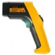
Manual Fluke 561


Summary
LIMITED WARRANTY AND LIMITATION OF LIABILITY This Fluke product will be free from defects in material and workmanship for two years from the date of purchase. This warranty does not cover fuses, disposable batteries, or damage from accident, neglect, misuse, alteration, contamination, or abnormal co...
i Table of Contents Title Page Introduction............................................................................................. 1 Contacting Fluke ...................................................................................... 1 Safety Information........................................
561 HVACPro Users Manual ii Measuring Grille, Register, or Diffuser Discharge Temperature ......... 15 Verifying Thermostat/Room Sensor Accuracy .................................... 15 Checking for Blockage in Air-To-Air Evaporators or Condensers........ 15 Checking Superheat on Fixed Restrictor or ...
Fluke Measuring Instruments Manuals
-
 Fluke 114
Manual
Fluke 114
Manual
-
 Fluke 175
Manual
Fluke 175
Manual
-
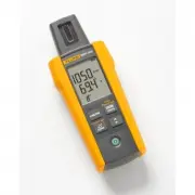 Fluke FLK-IRR1-SOL
User Manual
Fluke FLK-IRR1-SOL
User Manual
-
 Fluke MT-8200-49A
User Manual
Fluke MT-8200-49A
User Manual
-
 Fluke PRV240
User Manual
Fluke PRV240
User Manual
-
 Fluke TI10
Manual
Fluke TI10
Manual
-
 Fluke TI20
Manual
Fluke TI20
Manual
-
 Fluke TI25
Manual
Fluke TI25
Manual
-
 Fluke TI40
Manual
Fluke TI40
Manual
-
 Fluke TI45
Manual
Fluke TI45
Manual
-
 Fluke TI50
Manual
Fluke TI50
Manual
-
 Fluke TI55
Manual
Fluke TI55
Manual
-
 Fluke TIR
Manual
Fluke TIR
Manual
-
 Fluke TIR1
Manual
Fluke TIR1
Manual
-
 Fluke VT02
Manual
Fluke VT02
Manual
-
 Fluke VT04
Manual
Fluke VT04
Manual
-
 Fluke VT04A
Manual
Fluke VT04A
Manual