Fluke 80_SERIES_V - Manuals
Fluke 80_SERIES_V Measuring Instrument – Manual in PDF format online.
Manuals:
Manual Fluke 80_SERIES_V
1

2

3

4

5

6

7

8

9

10

11

12

13

14

15

16

17

18

19

20

21

22

23

24

25

26

27

28

29

30

31

32

33

34

35

36

Summary
Page 2 - Lifetime Limited Warranty
Lifetime Limited Warranty Each Fluke 20, 70, 80, 170 and 180 Series DMM will be free from defects in material and workmanship for its lifetime. As used herein, “lifetime” is defined as seven years after Fluke discontinues manufacturing the product, but the warranty period shall be at least ten years...
Page 3 - Table of Contents; Title
i Table of Contents Title Page Introduction........................................................................................................ 1 Contacting Fluke ................................................................................................ 1 Precautions and Safety Information...
Page 4 - ii
Fluke Measuring Instruments Manuals
-
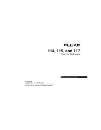 Fluke 114
Manual
Fluke 114
Manual
-
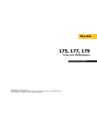 Fluke 175
Manual
Fluke 175
Manual
-
 Fluke 561
Manual
Fluke 561
Manual
-
 Fluke 19800HD9
User Manual
Fluke 19800HD9
User Manual
-
 Fluke FLK-IRR1-SOL
User Manual
Fluke FLK-IRR1-SOL
User Manual
-
 Fluke FLK-T3000 FC
User Manual
Fluke FLK-T3000 FC
User Manual
-
 Fluke FLUKE- 1507
User Manual
Fluke FLUKE- 1507
User Manual
-
 Fluke FLUKE-1AC-A1-II-LW
User Manual
Fluke FLUKE-1AC-A1-II-LW
User Manual
-
 Fluke FLUKE-9040
User Manual
Fluke FLUKE-9040
User Manual
-
 Fluke FLUKE-971
User Manual
Fluke FLUKE-971
User Manual
-
 Fluke FLUKE-CO-220
User Manual
Fluke FLUKE-CO-220
User Manual
-
 Fluke MT-8200-49A
User Manual
Fluke MT-8200-49A
User Manual
-
 Fluke PRV240
User Manual
Fluke PRV240
User Manual
-
 Fluke ST120+-LW
User Manual
Fluke ST120+-LW
User Manual
-
 Fluke ST120-LW
User Manual
Fluke ST120-LW
User Manual
-
 Fluke TI10
Manual
Fluke TI10
Manual
-
 Fluke TI20
Manual
Fluke TI20
Manual
-
 Fluke TI25
Manual
Fluke TI25
Manual
-
 Fluke TI40
Manual
Fluke TI40
Manual
-
 Fluke TI45
Manual
Fluke TI45
Manual