Dell Inspiron 8000 - User Manual

Dell Inspiron 8000 – User Manual, read for free online in PDF format. We hope this helps you resolve any issues you may have. If you have further questions, please contact us through the contact form.


Table of Contents:
- Page 2 – Recommended Tools; Screw Identification
- Page 3 – Screw Placemat
- Page 5 – System Components
- Page 6 – Hard Drive; Removing the Hard Drive
- Page 7 – Replacing the Hard Drive; Fixed Optical Drive
- Page 8 – Removing the Fixed Optical Drive; Media Bay Devices; Removing Media Bay Devices; Memory Modules
- Page 9 – Removing the Memory Module Cover
- Page 10 – Removing Memory Modules; Replacing Memory Modules
- Page 11 – Mini PCI Card Assembly; Removing the Mini PCI Card Assembly
- Page 12 – Replacing the Mini PCI Card Assembly
- Page 13 – Keyboard Assembly
- Page 14 – Removing the Keyboard Assembly
- Page 16 – Replacing the Keyboard Assembly
- Page 17 – Display and Bezel Assembly
- Page 18 – Removing the Hinge Cover
- Page 19 – Removing the Display Assembly
- Page 21 – Display Assembly Bezel and Panel
- Page 22 – Removing the Display Assembly Bezel; Removing the Display Panel
- Page 24 – Replacing the Display Panel
- Page 25 – Display Latch Assembly
- Page 27 – Microprocessor Thermal Cooling
- Page 28 – Removing the Microprocessor Thermal Cooling Assembly
- Page 29 – Microprocessor Module; Removing the Microprocessor Module
- Page 30 – Replacing the Microprocessor Module
- Page 33 – Video Card; Removing the Video Card
- Page 34 – Replacing the Video Card; Palm Rest Assembly; Removing and Replacing the Palm Rests
- Page 36 – Removing the Palm Rest Assembly
- Page 38 – Reserve Battery; Removing the Reserve Battery
- Page 39 – Replacing the Reserve Battery
- Page 40 – System Board Assembly
- Page 41 – Removing the System Board
- Page 44 – Removing and Replacing the Battery and Media Bay Latch
- Page 45 – Battery Charger Board; Removing the Battery Charger Board
- Page 46 – Replacing the Battery Charger Board; LED Board
- Page 47 – Removing the LED Board; Replacing the LED Board; Fan Assembly
- Page 48 – Removing the Fan Assembly
- Page 49 – Removing the Protective Covers From the RJ-11 and RJ-45
D e l l ™ I n s p i r o n ™ 8 0 0 0 : Re m o v i n g a n d R e p l a c i n g Pa r t s
73
D e l l ™ I n s p i r o n ™ 8 0 0 0 :
R e m o v i n g a n d
R e p l a c i n g P a r t s
Preparing to Work Inside the
Computer
N O T IC E :
Only a certified service technician should perform repairs on your
computer. Damage or inoperability due to servicing not authorized by Dell is
not covered by your warranty.
N O T IC E :
Unless otherwise noted, each procedure in this manual assumes that
a part can be replaced by performing the removal procedure in reverse order.
N O T IC E :
To avoid damaging the computer, perform the following steps before
you begin working inside the computer.
1
Make sure that the work surface is clean to prevent scratching the
computer cover.
2
Save and close any open files, and exit any open programs.
H I N T:
Make sure the
computer is turned off and
not in standby or
hibernate mode. If you
cannot shut down the
computer using the
computer’s operating
system, press and hold the
power button for 4
seconds.
3
Turn off the computer and all attached devices.
4
Make sure the computer is undocked.
5
Disconnect the computer from the electrical outlet.
6
To avoid possible damage to the system board, wait 10 to 20 seconds
and then disconnect any attached devices.
7
Disconnect all other external cables from the computer.
8
Remove any installed PC Cards or plastic blanks from the PC Card
slot.
9
Close the display and turn the computer upside down on a flat work
surface.
10
Remove the primary battery from the battery bay and the secondary
battery from the media bay, if a secondary battery is in use.
N O T IC E :
To avoid damaging the system board, you must remove the main
battery and secondary battery (if present) before you service the computer.
"Loading the manual" means you need to wait until the file loads and becomes available for online reading. Some manuals are very large, and the time they take to appear depends on your internet speed.
Was this manual helpful?
About this manual
- Brand
- Dell
- Model
- Inspiron 8000
- Document type
- User Manual
- Language(s)
- English
- Pages
- 51
- File size
- 1.6 MB
- Format
Summary
74 D e l l ™ I n s p i r o n ™ 8 0 0 0 : Re m o v i n g a n d Re p l a c i n g Pa r t s w w w .d e ll.c om | s u p p o rt .d e ll.c om 11 Remove any installed device in the media bay. 12 To dissipate any static electricity while you work, periodically touch an unpainted metal surface on the surface ...
D e l l ™ I n s p i r o n ™ 8 0 0 0 : Re m o v i n g a n d R e p l a c i n g Pa r t s 75 N O T IC E : When reinstalling a screw, you must use a screw of the correct diameter and length. Make sure that the screw is properly aligned with its corresponding hole, and avoid over tightening. Screw Placema...
D e l l ™ I n s p i r o n ™ 8 0 0 0 : Re m o v i n g a n d R e p l a c i n g Pa r t s 77 System Components display assembly keyboard palm rest assembly main battery bottom case assembly system board fixed optical drive hard drive storage module thermal coolingassembly hinge cover
Ask a question
Related manuals
Popular Dell Other
More Dell Other models
 Dell Inspiron 5000 User Manual
 Dell Inspiron 5000e Quick Guide
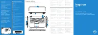 Dell Inspiron 5523 User Manual
 Dell Inspiron 5721 User Manual
- Dell Inspiron 7000 User Manual
 Dell Inspiron 7500 User Manual
 Dell Inspiron 8100 User Manual
 Dell Inspiron 8200 User Manual
 Dell Inspiron 8500 User Manual
 Dell Inspiron 8600 User Manual
 Dell Inspiron 9100 User Manual
- Dell Inspiron 9300 User Manual