Page 2 - Documentation Links: DellTM InspironTM 5000 Series; Document Title
Back to Contents Page Documentation Links: Dell™ Inspiron™ 5000 Series Printed Documentation To save PDF files (files with an extension of .pdf ) to your hard-disk drive, right-click the document title, click Save Target As in Microsoft ® Internet Explorer or Save Link As in Netscape Navigator, a...
Page 5 - Drivers and Utilities for Microsoft; Overview; Installing Drivers and Utilities for Windows; System Software CD
Back to Contents Page Drivers and Utilities for Microsoft ® Windows ® 2000: Dell™ Inspiron™ 5000 Series Overview This section explains how to install or reinstall Dell-provided device drivers and utilities on your Dell computer running the Microsoft Windows 2000 operating system. You may need to...
Page 6 - Installing the Audio Driver
Installing Windows 2000 Perform the following steps to install the Windows 2000 operating system on the hard-disk drive before you install any device drivers or utilities: 1. Insert the Dell Products Recovery CD into the CD-ROM or DVD-ROM drive. 2. Shut down the computer. 3. Turn on the computer. ...
Page 7 - Installing the Video Driver; Installing the Touch Pad Driver
The audio driver allows you to customize the sound features of your computer. 1. Save and close any open files, and exit any open application programs. 2. Insert the System Software CD into the CD-ROM or DVD-ROM drive. 3. Click the Start button, and then click Run . 4. In the Run dialog box, type x ...
Page 8 - Installing the Software DVD Decoder Driver (Optional)
3. Click the Start button, and then click Run . 4. In the Run dialog box, type x :\win2000\touchpad\english\setup.exe , where x is the CD-ROM or DVD-ROM drive letter. If you are using a Japanese-language version of Windows, type x :\win2000\touchpad\japanese\setup.exe , where x is the CD-ROM or DVD-...
Page 9 - Setting and Changing the DVD-ROM Drive Code; Installing the Intel; Updating Drivers and Utilities
8. Click OK . Setting and Changing the DVD-ROM Drive Code If you reinstall the DVD decoder software, you must set the DVD-ROM drive region code before you can play a movie. The region code can be reset if you relocate to another region. To reset the drive region code, perform the following steps: 1....
Page 12 - Installing Windows Me
Installing Windows Me Perform the following steps to install the Windows Me operating system on the hard-disk drive before you install any device drivers or utilities: 1. Turn on the computer and enter the system setup program. 2. In the system setup program Boot menu, change the boot sequence so ...
Page 14 - Installing Softex BayManager
Installing the Touch Pad Driver The touch pad driver controls touch pad and mouse functions. 1. Save and close any open files, and exit any open application programs. 2. Insert the System Software CD into the CD-ROM or DVD-ROM drive. 3. Click the Start button, and then click Run . 4. In the Run di...
Page 18 - Boot Your Computer With the System Software CD
The Enter Windows Properties window appears. To continue without creating a Windows user name and password, click OK . Otherwise, type your user name and password in the appropriate fields and then click OK . 16. If the Date/Time Properties window appears, adjust the date and time properties, click ...
Page 19 - Delete the Hibernate File; Create the Hibernate File; Enable Hibernate Support
10. Press the down-arrow key to select Exit to MS-DOS and then press <Enter>. For instructions on deleting the hibernate file, see "Delete the Hibernate File." Delete the Hibernate File 1. Boot your computer from the CD-ROM or DVD-ROM drive with the System Software CD in the CD-ROM o...
Page 20 - View the Hibernate File Information
4. Ensure that Enable hibernate support is selected and click Apply . 5. Click OK to close the Control Panel . View the Hibernate File Information 1. Boot your computer from the CD-ROM or DVD-ROM drive with the System Software CD in the CD-ROM or DVD-ROM drive. For instructions, see " Boot You...
Page 22 - Installing the Internal Modem Driver (Optional)
To uninstall Softex BayManager, perform the following steps: 1. Save and close any open files, and exit any open application programs. 2. Click Start , select Settings , and then click Control Panel . 3. Double-click Add/Remove Programs . 4. Select Softex BayManager and click Add/Remove . 5. Follow ...
Page 25 - Technical Overview: DellTM InspironTM 5000 Series; New Features; Hardware Overview
Back to Contents Page Technical Overview: Dell™ Inspiron™ 5000 Series New Features Most of the core technology implemented in the Inspiron 5000 series existed previously on other Dell portable computers. The Inspiron 5000 series has the following new key features: l A 3-spindle, 7.5-pound chassis ...
Page 27 - Back View
Back View 1 Display locking tabs 8 Display latches 2 Display 9 Battery bay 3 Display-close button 10 Microphone 4 Keyboard 11 Power button 5 Touch pad 12 Keyboard status indicators 6 Touch pad buttons 13 Device access/status indicators 7 Media bay 1 Fan exhaust 6 Docking connector 2 Serial po...
Page 29 - Bottom View
Bottom View Back to Contents Page 1 Security cable slot 4 PC Card slot 2 Display latch (one of two) 5 AC adapter connector 3 Speaker (one of two) 6 Air intake 1 Battery bay 4 Hard-disk drive 2 Media bay 5 Modem cover 3 Strike zone 6 Memory module cover
Page 30 - Ports and Connectors: DellTM InspironTM 5000 Series; I/O Connector Locations
Back to Contents Page Ports and Connectors: Dell™ Inspiron™ 5000 Series I/O Connector Locations Serial Port Connector Use the 9-pin serial port connector to attach a serial device to the computer. The serial port passes data in serial format (1 bit at a time over one line). This port supports a ...
Page 31 - Parallel Port Connector
Parallel Port Connector Use the 25-hole parallel port connector to attach a parallel device to the computer. The parallel port connector is used primarily for printers. The parallel port transmits data in parallel format, where 8 data bits (one byte) are sent simultaneously over eight separate lin...
Page 33 - USB Connector
USB Connector Use the Universal Serial Bus (USB) connector to attach one or more USB devices, such as a mouse, to the computer. USB is a peripheral bus standard that enables automatic detection of USB-compliant peripheral devices. PS/2 Connector Use the 6-hole, miniature Deutsche Industrie...
Page 35 - Conserving Power: DellTM InspironTM 5000 Series; Conservation Tips; Standby Mode; Hibernate Mode
Back to Contents Page Conserving Power: Dell™ Inspiron™ 5000 Series Conservation Tips l You automatically conserve battery power each time you attach your computer to an electrical outlet. When the AC adapter is attached, the battery is charged while the computer uses AC power. Your battery's life...
Page 36 - Power Options Properties; Power Schemes Tab
To exit hibernate mode, press the power button. The computer may take a short time to return to its typical operating state. Power Options Properties To access the Power Options Properties window: Power Schemes Tab The Power schemes pulldown menu displays the selected preset power scheme: l Port...
Page 37 - Power Meter Tab; Advanced Tab
Power Meter Tab The Power Meter tab displays the current power source and amount of battery charge remaining. Advanced Tab The Advanced tab allows you to: l Set icon and standby password options. l Program the following functions: — Activate standby mode (default when you close the display). —...
Page 40 - Removing and Replacing Parts: DellTM InspironTM 5000 Series; Precautionary Measures; WARNING: FOR YOUR PERSONAL SAFETY AND PROTECTION OF THE EQUIPMENT:
Back to Contents Page Removing and Replacing Parts: Dell™ Inspiron™ 5000 Series Click here to view a printable (.pdf) version of the disassembly instructions. Overview Unless otherwise noted, each procedure assumes the following: l You have the recommended tools. l You have performed the steps in ...
Page 44 - Screw Counts and Locations
8. Remove the device from the media bay: a. Close the display and turn the computer upside-down. b. Slide and hold the latch release away from the media bay device. c. Pull the device out of the media bay. Screw Counts and Locations You may find it helpful to print the following table to use for k...
Page 45 - ZIF Connectors; Modem Removal
ZIF Connectors Some of the interface connectors are zero insertion force (ZIF) connectors. These connectors are not removable; they must be released to disconnect a cable from them. To disconnect a cable from a ZIF connector, perform the following steps: 1. Insert a small flat-blade screwdriver, d...
Page 46 - Hinge Cover Removal
Ensure that all precautionary measures have been followed and that all customer-accessible parts are removed. 1. Remove the modem cover. 2. Spread the release tabs on either side of the modem away from the modem. 3. Remove the modem. 4. Remove the modem cable. To reinsert the modem when you reassemb...
Page 47 - Keyboard Removal
2. Open the display, and lift off the hinge cover by rotating it toward you. To replace the hinge cover, perform the following steps: 1. Insert the hinge cover at a 45° angle. 2. Press the hinge cover down above the <F4>, <F5>, and <Print Screen> keys. 3. Press down along the enti...
Page 48 - Thermal Shield Removal
Thermal Shield Removal 1. Remove the thermal shield screws. Inspiron 5000 computers have 4 screws (first photo), and Inspiron 5000e computers have 5 screws (second photo). NOTICE: Only a certified service technician should perform repairs on your computer. Damage or inoperability due to servicin...
Page 49 - Processor Module Removal
2. Remove the diskette-drive cable clip (held in place by the leftmost thermal shield screw). 3. Lift off the thermal shield. Processor Module Removal 1. Remove the processor module screws. Inspiron 5000 computers have 3 screws (first photo), and Inspiron 5000e computers have 2 screws (second phot...
Page 50 - LCD Removal; Video Board Removal
2. Lift out the module. 3. When you replace the processor, be sure to attach it to the connector. When you replace the processor during reassembly, be sure to attach it to the connector. LCD Removal 1. Open the display and disconnect the LCD flex cable. 2. Close the display and remove the four LCD...
Page 51 - Diskette Drive Removal
1. Remove the screw. 2. Disconnect the touch pad cable. Diskette Drive Removal 1. Detach the data cable. 2. Remove the drive retaining screws from the bottom of the computer. NOTICE: Only a certified service technician should perform repairs on your computer. Damage or inoperability due to servici...
Page 52 - Palmrest Removal
3. Remove the drive from the chassis. Palmrest Removal 1. Remove the three screws from the top of the computer. 2. Remove the two screws (outer corners) from the bottom of the computer. If you plan to remove the system board, also remove the three screws adjacent to the memory module slots and the...
Page 54 - Speaker and Volume Board Removal
5. Remove the five screws from the media bay. Speaker and Volume Board Removal 1. Remove the nine screws. 2. Disconnect the speaker cable. Be sure to carefully remove the Kapton tape that holds the speaker cable in position on the left side. 3. Disconnect the volume cable. Support Rail Removal N...
Page 55 - Infrared Board Removal
1. Remove the four screws. 2. Disconnect the fan cable. 3. Remove the seven screws from the back of the computer. Infrared Board Removal Disconnect the infrared board from the system board. servicing not authorized by Dell is not covered by your warranty. NOTICE: Only a certified service technicia...
Page 56 - System Board Removal
System Board Removal 1. Remove the two screws. 2. Remove the eight I/O port nuts. NOTICE: Only a certified service technician should perform repairs on your computer. Damage or inoperability due to servicing not authorized by Dell is not covered by your warranty.
Page 57 - Bezel Removal
3. Flex the base plastics to separate the system board from the audio connector posts on the left side of the computer. 4. Lift the system board up and out from the base plastics. 14.1-Inch XGA Display Disassembly Bezel Removal 1. Remove the two screw covers from the bottom corners of the LCD beze...
Page 58 - Panel Removal; LED/Inverter Board Removal
5. Once you have disengaged all of the retaining tabs, lift the bezel from the LCD panel. Panel Removal 1. Remove the two screws from each side of the panel. 2. Disconnect the cold cathode fluorescent lamp (CCFL) cable from the bottom of the panel. 3. Disconnect the flex cable from the back of the L...
Page 60 - System Setup Program: DellTM InspironTM 5000 Series; Using the System Setup Program; Navigating Through the System Setup Program
Back to Contents Page System Setup Program: Dell™ Inspiron™ 5000 Series Using the System Setup Program The computer retains system configuration information in the nonvolatile random-access memory (NVRAM) maintained by the reserve battery. Each time you turn on the computer, the system compares th...
Page 62 - Security Menu
Security Menu Option Function IDE Controller Configures the integrated local-bus IDE adapter. Options are Both (default), Disabled , or Primary . If Both is selected, you can access both the hard-disk drive and the media bay device(s). If Primary is selected, only the hard-disk drive and megabit...
Page 63 - Power Menu
Power Menu Option Function System Password is If no system password is set, the setting is Clear . Otherwise, the setting is Set . Set System Password Press <Enter> to set up a new system password, and then follow the instructions on your screen. This password restricts access to the sys...
Page 64 - Boot Menu
Boot Menu setting. Max. Power Savings conserves the maximum amount of system power, and Max. Performance conserves power but allows the greatest system performance. Standby Time-out Lets you determine how long the computer remains idle (no I/O activity) before activating standby mode to conserve...
Page 65 - Exit Menu
Exit Menu Back to Contents Page Internal Hard Drive The computer boots only from the hard-disk drive. If it fails to boot from the hard-disk drive, the computer does not attempt to boot from the diskette drive. CD-ROM/DVD Causes the computer to attempt to boot first from a bootable CD. If it doe...
Page 66 - Technical Specifications: DellTM InspironTM 5000 Series; Microprocessor
Back to Contents Page Technical Specifications: Dell™ Inspiron™ 5000 Series Microprocessor Inspiron 5000 Inspiron 5000e Microprocessor Physical Chip Set and Bus Keyboard PC Card Slot Touch Pad Memory Battery Connectors AC Adapter Integrated Audio Environmental Video Regulatory Microprocessor ...
Page 68 - Connectors
Connectors 192 MB 128 MB 320 MB 192 MB 192 MB 384 MB 192 MB 256 MB 448 MB 256 MB 32 MB 288 MB 256 MB 64 MB 320 MB 256 MB 128 MB 384 MB 256 MB 192 MB 448 MB 256 MB 256 MB 512 MB *Not all valid memory configurations are available at all times. Contact Dell for details. Upper Memory Map Locatio...
Page 71 - Physical
Physical 1600 x 1200 32 bit 60 NOTES: If using an external monitor, see the documentation that came with the external monitor to determine the correct refresh rate. You may need to adjust the vertical and horizontal size and position controls on your external monitor to properly display extend...
Page 74 - Regulatory
Regulatory Back to Contents Page Relative humidity 10% to 90% (noncondensing) Maximum vibration: Operating 0.9 GRMS using a random-vibration spectrum that simulates air/truck shipment Storage 1.3 GRMS using a random-vibration spectrum that simulates air/truck shipment Maximum shock:* Operating 1.5...
Page 75 - System Messages: DellTM InspironTM 5000 Series
Back to Contents Page System Messages: Dell™ Inspiron™ 5000 Series Overview The operating system, application programs, and the computer itself can generate status and error information. This section explains the system messages generated by the basic input/output system (BIOS). For other messages...


 Dell Inspiron 3646 User Manual
 Dell Inspiron 3700 User Manual
 Dell Inspiron 3800 User Manual
 Dell Inspiron 4000 User Manual
 Dell Inspiron 4100 User Manual
 Dell Inspiron 4150 User Manual
 Dell Inspiron 5000e Quick Guide
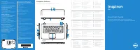 Dell Inspiron 5523 User Manual
 Dell Inspiron 5721 User Manual
 Dell Inspiron 7500 User Manual
 Dell Inspiron 8000 User Manual