Page 3 - A Tour of Your Computer; Front View
A Tour of Your Computer : Dell Inspiron 8100 Back to Contents Page A Tour of Your Computer Dell™ Inspiron™ 8100 Front View Left Side View Right Side View Back View Front View file:///F|/Service%20Manuals/Dell/Inspiron/8100/tour.htm (1 of 18) [2/28/2004 7:37:11 AM]
Page 4 - Display Latch; Device Status Lights
A Tour of Your Computer : Dell Inspiron 8100 Display Latch This latch keeps the display locked in place when the display is closed. Display The computer has a color LCD. Device Status Lights file:///F|/Service%20Manuals/Dell/Inspiron/8100/tour.htm (2 of 18) [2/28/2004 7:37:11 AM]
Page 6 - Air Intake; Keyboard Status Lights
A Tour of Your Computer : Dell Inspiron 8100 ❍ Solid orange, which indicates that the battery charge is critically low NOTICE: To avoid data loss, never turn off the computer while the green light labeled is flashing. Air Intake HINT: The computer turns on the fans only when the computer gets hot. T...
Page 7 - Track Stick
A Tour of Your Computer : Dell Inspiron 8100 The green lights located above the keyboard indicate the following: ● The light labeled turns on when you press to enable the numeric keypad. ● The light labeled turns on when you press to enable the uppercase letter function. ● The light labeled turns on...
Page 9 - Microphone; Volume Control Buttons; DellTM AccessDirectTM Buttons
A Tour of Your Computer : Dell Inspiron 8100 Microphone The internal microphone allows you to record voice audio. Volume Control Buttons Increase or decrease the speaker volume with the volume control buttons. You can also change the speaker volume using key combinations: ● To increase the volume pr...
Page 10 - Left Side View
A Tour of Your Computer : Dell Inspiron 8100 HINT: To launch the Dell Solution Center, the computer must be turned on and functioning properly. 1 Press this button to launch the Dell Solution Center, where you can find support and educational tools that Dell has installed on your computer. 2 Press t...
Page 11 - Security Cable Slot; Speakers
A Tour of Your Computer : Dell Inspiron 8100 Security Cable Slot The slots (one on each side of the computer) let you attach a commercially available antitheft device to the computer. Complete instructions for installing antitheft devices are usually included with the device. NOTICE: Antitheft devic...
Page 12 - Fixed Optical Drive; Right Side View
A Tour of Your Computer : Dell Inspiron 8100 Your computer has integrated speakers. Press the volume control buttons to adjust the speaker volume. S-Video TV-Out Connector Use this connector to connect your computer to a television. If you have a TV/digital audio adapter cable, you can also connect ...
Page 13 - Audio Connectors
A Tour of Your Computer : Dell Inspiron 8100 Audio Connectors file:///F|/Service%20Manuals/Dell/Inspiron/8100/tour.htm (11 of 18) [2/28/2004 7:37:11 AM]
Page 14 - Infrared Sensor
A Tour of Your Computer : Dell Inspiron 8100 ● Attach record/playback devices such as a cassette player or CD player to the connector. ● Attach headphones or speakers to the connector. ● Attach a microphone to the connector. IEEE 1394 Connector Use this connector to attach IEEE 1394-compatible devic...
Page 15 - Hard Drive; Modem Connector; Network Connector
A Tour of Your Computer : Dell Inspiron 8100 HINT: The infrared sensor does not function when the computer is connected to a port replicator. Hard Drive The hard drive reads and writes data on a hard disk. Modem Connector If you ordered the optional internal modem, use this connector to plug in the ...
Page 16 - PC Card Slot
A Tour of Your Computer : Dell Inspiron 8100 If you ordered the optional integrated network adapter, use this connector to connect the computer to a network. Security Cable Slot The slots (one on each side of the computer) let you attach a commercially available antitheft device to the computer. Com...
Page 17 - Back View; Fan Exhausts; AC Adapter Connector
A Tour of Your Computer : Dell Inspiron 8100 Back View Fan Exhausts HINT: The computer turns on the fan only when the computer gets hot. It may run most of the time or very seldom, depending on your use of the computer. Because the fan spins at a high rate of speed, it may make a noise. This noise i...
Page 18 - Parallel Connector; USB Connectors
A Tour of Your Computer : Dell Inspiron 8100 HINT: Although the AC adapter works worldwide, power connectors vary among countries. Before using the AC adapter in a foreign country, you may need to obtain a new power cable designed for use with the electrical outlets in that country. The AC adapter c...
Page 19 - Serial Connector
A Tour of Your Computer : Dell Inspiron 8100 Use these connectors to attach USB-compatible devices such as a mouse, keyboard, printer, or scanner to your computer. Serial Connector Use this connector to attach a serial device to the computer. HINT: The port replicator may not be available in certain...
Page 21 - Power Conservation; Conservation Tips; Power Conservation Modes; Standby Mode
Power Conservation : Dell Inspiron 8100 Back to Contents Page Power Conservation Dell™ Inspiron™ 8100 Conservation Tips Power Conservation Modes Power Options Properties Conservation Tips ● You automatically conserve battery power each time you attach your computer to an electrical outlet. When the ...
Page 22 - Hibernate Mode
Power Conservation : Dell Inspiron 8100 standby mode. To activate standby mode: ● Click the Start button, click Shut down , click Stand by , and then click OK . or ● Press the power button or the power conservation key combination, <Fn><Suspend>, that you programmed (via the Advanced tab...
Page 23 - Power Options Properties; Power Schemes Tab
Power Conservation : Dell Inspiron 8100 Hibernate mode requires a special file on your hard drive with enough disk space to store the contents of the computer memory. Dell creates an appropriately sized hibernate mode file before shipping the computer to you. If you reinstall the operating system, y...
Page 24 - Alarms Tab
Power Conservation : Dell Inspiron 8100 Alarms Tab HINT: To enable audible alarms, click each Alarm Action button and select Sound alarm . The Low battery alarm and Critical battery alarm settings alert you with a message when the battery charge falls below a certain percentage. When you receive you...
Page 25 - Hibernate Tab
Power Conservation : Dell Inspiron 8100 Hibernate Tab The Hibernate tab lets you enable hibernate mode by clicking the Enable hibernate support check box. Back to Contents Page file:///F|/Service%20Manuals/Dell/Inspiron/8100/power.htm (5 of 5) [2/28/2004 7:37:12 AM]
Page 26 - Solving Problems; Accessing Help Files
Solving Problems : Dell Inspiron 8100 Back to Contents Page Solving Problems Dell™ Inspiron™ 8100 Accessing Help Files Power Problems Start-Up Error Messages Video and Display Problems Sound and Speaker Problems Printer Problems Modem Problems Scanner Problems Touch Pad Problems External Keyboard Pr...
Page 27 - Power Problems
Solving Problems : Dell Inspiron 8100 To access Microsoft® Windows® 2000 Help 1. Click the Start button and then click Help . 2. Click the Search tab. 3. Type a word or phrase that describes your problem and then click List Topics . 4. Click the topic that describes your problem and then click Displ...
Page 28 - Start-Up Error Messages; Video and Display Problems; If the display is blank
Solving Problems : Dell Inspiron 8100 Check the AC adapter— Be sure that the power cable is firmly inserted into the electrical outlet and the green light on the AC adapter is on. Connect the computer directly to an electrical outlet— Bypass power protection devices, power strips, and the extension ...
Page 29 - If the display is difficult to read
Solving Problems : Dell Inspiron 8100 Check the power light— When the power light is lit or blinking, the computer has power. If the power light is blinking, the computer is in standby mode—press the power button to exit standby mode. If the power light is off, press the power button. Check the batt...
Page 30 - Sound and Speaker Problems; Integrated Speakers; External Speakers
Solving Problems : Dell Inspiron 8100 Adjust the Windows display settings— 1. Click the Start button, point to Settings , and then click Control Panel . 2. Double-click the Display icon and then click the Settings tab. 3. Try different settings for Colors and Screen area . Sound and Speaker Problems...
Page 31 - Printer Problems; If you cannot print to a parallel port printer
Solving Problems : Dell Inspiron 8100 Ensure that the speakers are turned on— See the setup diagram supplied with the speakers. Adjust the speaker controls— Adjust the volume, bass, or treble controls to eliminate distortion. Adjust the Windows volume control— Double-click the yellow speaker icon in...
Page 32 - If you cannot print to a USB printer
Solving Problems : Dell Inspiron 8100 Ensure that the printer is turned on— See the documentation supplied with the printer. Verify that the printer is recognized by Windows— 1. Click the Start button, point to Settings , and then click Printers . If the printer is listed, right-click the printer ic...
Page 33 - Modem Problems
Solving Problems : Dell Inspiron 8100 Modem Problems NOTICE: Connect the modem to an analog telephone wall jack only. Connecting the modem to a digital telephone network damages the modem. Check the telephone jack— Disconnect the telephone line from the modem and connect it to a telephone. Listen fo...
Page 34 - Scanner Problems; External Keyboard Problems
Solving Problems : Dell Inspiron 8100 Scanner Problems Check the power cable connection— Ensure that the scanner power cable is firmly connected to a working electrical power source and that the scanner is turned on. Check the scanner cable connection— Ensure that the scanner cable is firmly connect...
Page 35 - Unexpected Characters; Drive Problems; If you cannot save a file to a floppy disk
Solving Problems : Dell Inspiron 8100 Unexpected Characters Disable the numeric keypad— Press the <Num Lk> key to disable the numeric keypad. Verify that the numbers lock light is not lit. Drive Problems HINT: For information on saving files to a floppy disk, see the Tell Me How help file. If ...
Page 36 - If you cannot play a music CD or install a
Solving Problems : Dell Inspiron 8100 If you cannot play a music CD or install a program from a CD HINT: High-speed CD drive vibration is normal and may cause noise. This noise does not indicate a defect in the drive or the CD. Ensure that Windows recognizes the drive— Double-click the My Computer i...
Page 37 - If you cannot play a DVD movie; If the CD-RW drive stops writing; If you have a hard drive problem
Solving Problems : Dell Inspiron 8100 If you have one CD in the fixed optical drive and one CD in the media bay drive— Identify which CD is not playing: 1. Double-click the My Compute r icon on your desktop. 2. Double-click the drive letter of the device the you are verifying. If you cannot play a D...
Page 38 - Network Problems; Windows® Error Messages
Solving Problems : Dell Inspiron 8100 Check the hard drive for errors— Windows Me: Click the Start button, point to Programs —> Accessories —> System Tools , and then click ScanDisk . Windows 2000: 1. Double-click the My Computer icon. 2. Right-click the Local Disk icon and then click Properti...
Page 39 - General Program Problems
Solving Problems : Dell Inspiron 8100 x:\ is not accessible. The device is not ready— Insert a disk into the drive and try again. A filename cannot contain any of the following characters: \ / : * ? " < > |— Do not use these characters in filenames. Not enough memory or resources. Close so...
Page 40 - A program crashes; A program stops responding; A solid blue screen appears
Solving Problems : Dell Inspiron 8100 A program crashes See the software documentation— Many software manufacturers maintain websites with information that may help you to solve the problem. A program stops responding Press <Ctrl><Alt><Del>— In the Close Program window, select the ...
Page 41 - If Your Computer Gets Wet
Solving Problems : Dell Inspiron 8100 If Your Computer Gets Wet CAUTION: Perform this procedure only after you are certain that it is safe to do so. If the computer is connected to an electrical outlet, Dell recommends that you turn off AC power at the circuit breaker before attempting to remove the...
Page 42 - If You Drop or Damage Your Computer; Resolving Other Technical Problems
Solving Problems : Dell Inspiron 8100 12. Replace the hard drive . 13. Replace the media bay device and any PC Cards you removed. 14. Replace the battery, and connect the computer to an electrical outlet. 15. Turn on the computer and verify that it is working properly. If the computer does not start...
Page 44 - System Specifications
System Specifications : Dell Inspiron 8100 Back to Contents Page System Specifications Dell™ Inspiron™ 8100 Microprocessor System Information PC Card Memory Ports and Connectors Video Audio Display Keyboard Touch Pad Track Stick Modem Battery AC Adapter Environmental Fixed Optical Drives Microproces...
Page 53 - Reinstalling Software; Overview
Reinstalling Software : Dell Inspiron 8100 Back to Contents Page Reinstalling Software Dell™ Inspiron™ 8100 Overview Reinstalling Drivers and Utilities Reinstalling Microsoft® Windows® Millennium Edition (Me) Reinstalling Windows 2000 Overview Dell provides software utilities and drivers that help y...
Page 54 - Reinstalling Drivers and Utilities
Reinstalling Software : Dell Inspiron 8100 HINT: Your Drivers and Utilities CD contains drivers for operating systems that may not be on your computer. Verify that the driver you are loading is under your operating system subdirectory. Dell recommends that you print these procedures before you begin...
Page 55 - Reinstalling the Internal Modem and Network; Reinstalling the Modem or Network Adapter Driver for
Reinstalling Software : Dell Inspiron 8100 A link appears for the specific driver or utility used by your computer. 7. Click the link to display the Languages screen. 8. Click your preferred language for the driver or utility (if available) or click Multiple . 9. Click the Install button (if present...
Page 57 - Reinstalling Microsoft® Windows®
Reinstalling Software : Dell Inspiron 8100 If you are reinstalling a modem driver, click PCI Simple Communications Controller . If you are reinstalling a network adapter, click Ethernet Controller . 7. From the pull-down menu, click Action , and select Properties . 8. Click the Reinstall Driver butt...
Page 59 - Enabling Hibernate Support
Reinstalling Software : Dell Inspiron 8100 Windows user name and password, click OK . Otherwise, type your user name and password in the appropriate fields, and then click OK . 16. If the Date/Time Properties window appears, adjust the date and time properties, click Apply , and then click OK . Wind...
Page 62 - System Setup Program; Standard Settings
System Setup Program : Dell Inspiron 8100 Back to Contents Page System Setup Program Dell™ Inspiron™ 8100 Standard Settings System Setup Program Pages Viewing the System Setup Program Pages Standard Settings The system setup program contains the standard settings for your computer. NOTICE: Unless yo...
Page 63 - Viewing the System Setup Program Pages
System Setup Program : Dell Inspiron 8100 ● Page 6 displays system security and hard drive password settings. Viewing the System Setup Program Pages 1. Turn on (or restart) your computer. 2. When the Dell™ logo appears, press <F2> immediately. If you wait too long and the Windows® logo appears...
Page 64 - Ports and Connector Pin-Outs
Ports and Connector Pin-Outs : Dell Inspiron 8100 Back to Contents Page Ports and Connector Pin-Outs Dell™ Inspiron™ 8100 Serial Connector Parallel Connector PS/2 Connector USB Connectors S-Video TV-Out Connector Video Connector Docking Connector IEEE-1394 Connector Serial Connector Pin Signal 1 DCD...
Page 68 - Video Connector
Ports and Connector Pin-Outs : Dell Inspiron 8100 Pin Signal 1 GND 2 GND 3 DLUMA-L 4 DCRMA-L 5 SPDIF 6 DCMPS-L 7 SPGND Video Connector file:///F|/Service%20Manuals/Dell/Inspiron/8100/pinouts.htm (5 of 10) [2/28/2004 7:37:17 AM]
Page 70 - Docking Connector
Ports and Connector Pin-Outs : Dell Inspiron 8100 Docking Connector Pin Signal Pin Signal Pin Signal Pin Signal 1 STRB#/5V 51 HSYNC 101 VGA_GRN 151 GND 2 PD0 52 VSYNC 102 GND 152 CLK_SPCI 3 PD1 53 GND 103 VGA_RED 153 GND 4 PD2 54 DOCKED 104 GND 154 SAD0 5 PD3 55 USB_VD1+ 105 VGA_BLU 155 SAD1 6 PD4 5...
Page 74 - Removing and Replacing Parts; Preparing to Work Inside the Computer
Removing and Replacing Parts : Dell Inspiron 8100 Back to Contents Page Removing and Replacing Parts Dell™ Inspiron™ 8100 Preparing to Work Inside the Computer Recommended Tools Screw Identification System Components Hard Drive Fixed Optical Drive Media Bay Devices Memory Modules Mini PCI Card Assem...
Page 76 - Recommended Tools
Removing and Replacing Parts : Dell Inspiron 8100 Recommended Tools ● Number 1 magnetized Phillips screwdriver ● Small flat-blade screwdriver ● Pry stick ● Small plastic scribe ● Microprocessor extractor ● Flash BIOS update program floppy disk or CD (required only when upgrading the microprocessor, ...
Page 77 - Screw Placemat
Removing and Replacing Parts : Dell Inspiron 8100 NOTICE: When reinstalling a screw, you must use a screw of the correct diameter and length. Make sure that the screw is properly aligned with its corresponding hole, and avoid over tightening. Screw Placemat Hard Drive Door Security :M3 x 5 mm (1 eac...
Page 78 - System Components
Removing and Replacing Parts : Dell Inspiron 8100 Display Bezel :Rubber screw covers (4 each)Plastic screw covers (2 each)M2.5 x 4 mm (6 each) Display Panel to Display Mounting Bracket :M2 x 3 mm (6 each) Flex-Cable Mounting Bracket to Top Cover :M2.5 x 4 mm (1 each) Video Card :M2.5 x 8 mm (3 each)...
Page 80 - Removing the Hard Drive
Removing and Replacing Parts : Dell Inspiron 8100 Hard Drive NOTICE: Disconnect the computer and attached devices from electrical outlets and remove any installed batteries. NOTICE: To avoid ESD, ground yourself by using a wrist grounding strap or by periodically touching an unpainted metal surface ...
Page 81 - Replacing the Hard Drive
Removing and Replacing Parts : Dell Inspiron 8100 NOTICE: The disk drive is very sensitive to shock. Handle the assembly by its edges (do not squeeze the top of the hard drive case), and avoid dropping it. 1. Follow the instructions in " Preparing to Work Inside the Computer ." 2. Close the ...
Page 82 - Removing the Fixed Optical Drive
Removing and Replacing Parts : Dell Inspiron 8100 NOTICE: Disconnect the computer and attached devices from electrical outlets and remove any installed batteries. NOTICE: To avoid ESD, ground yourself by using a wrist grounding strap or by periodically touching an unpainted metal surface on the comp...
Page 83 - Media Bay Devices; Removing Media Bay Devices; Memory Modules; Removing the Memory Module Cover
Removing and Replacing Parts : Dell Inspiron 8100 Media Bay Devices NOTICE: Disconnect the computer and any attached devices from electrical outlets, and remove any installed batteries. NOTICE: To avoid ESD, ground yourself by using a wrist grounding strap or by periodically touching an unpainted me...
Page 84 - Removing Memory Modules
Removing and Replacing Parts : Dell Inspiron 8100 NOTICE: Make sure that the work surface is clean to prevent scratching the computer cover. NOTICE: Handle memory modules with care. Do not touch the components on a module. Hold a module by its edges. 1. Follow the instructions in " Preparing to ...
Page 85 - Replacing Memory Modules
Removing and Replacing Parts : Dell Inspiron 8100 1. Remove the memory module cover . 2. To release a memory module from its connector, spread apart the tabs at each side of the module until the module pops up slightly. 3. Lift the memory module out of its connector. Replacing Memory Modules HINT: M...
Page 86 - Mini PCI Card Assembly; Removing the Mini PCI Card Assembly
Removing and Replacing Parts : Dell Inspiron 8100 3. Pivot the memory module down until it clicks into place. If you do not hear a click, remove the module and reinstall it. 4. Insert the metal tabs on the memory module cover into the bottom case assembly. Rotate the cover down and replace the screw...
Page 87 - Replacing the Mini PCI Card Assembly
Removing and Replacing Parts : Dell Inspiron 8100 3. To release the Mini PCI card assembly, spread the metal securing tabs until the assembly pops up slightly. 4. Disconnect the assembly from the wiring harness or internal antenna. 5. Lift out the assembly and disconnect any attached cables. Replaci...
Page 89 - Keyboard Assembly
Removing and Replacing Parts : Dell Inspiron 8100 NOTICE: If a wireless network adapter card contains two mini-coax antenna connectors, connect the mini-coax cable to the outermost antenna connector as shown. NOTICE: If you are installing a wireless network adapter, fold and tuck the unused wiring h...
Page 90 - Removing the Keyboard Assembly
Removing and Replacing Parts : Dell Inspiron 8100 NOTICE: Disconnect the computer and attached devices from electrical outlets and remove any installed batteries. NOTICE: To avoid ESD, ground yourself by using a wrist grounding strap or by periodically touching an unpainted metal surface on the comp...
Page 92 - Replacing the Keyboard Assembly
Removing and Replacing Parts : Dell Inspiron 8100 7. Disconnect the keyboard cable and lay the keyboard assembly aside. Replacing the Keyboard Assembly 1. While bracing the keyboard assembly upright on its left end, connect the keyboard cable to the interface connector on the system board. NOTICE: P...
Page 93 - Display and Bezel Assembly
Removing and Replacing Parts : Dell Inspiron 8100 3. Check that the keyboard is correctly installed. The keys should be flush with the left and right surfaces of the palm rest. 4. Reinstall the four screws in the holes labeled "circle K." Display and Bezel Assembly file:///F|/Service%20Manua...
Page 94 - Removing the Hinge Cover; Removing the Display Assembly
Removing and Replacing Parts : Dell Inspiron 8100 NOTICE: Disconnect the computer and attached devices from electrical outlets and remove any installed batteries. NOTICE: To avoid ESD, ground yourself by using a wrist grounding strap or by periodically touching an unpainted metal surface on the comp...
Page 96 - Display Assembly Bezel and Panel
Removing and Replacing Parts : Dell Inspiron 8100 NOTICE: When reconnecting the flex cable, press down on both ends of the connector, not in the middle. Pressing the middle of the connector can damage fragile components. 3. Open the display and remove the two screws (marked with a "circle D"...
Page 98 - Removing the Display Assembly Bezel; Removing the Display Panel
Removing and Replacing Parts : Dell Inspiron 8100 NOTICE: To avoid ESD, ground yourself by using a wrist grounding strap or by periodically touching an unpainted metal surface on the computer. Removing the Display Assembly Bezel 1. Follow the instructions in " Preparing to Work Inside the Comput...
Page 100 - Replacing the Display Panel
Removing and Replacing Parts : Dell Inspiron 8100 Replacing the Display Panel HINT: Use a magnetic screwdriver to reassemble the display panel in the display. 1. Connect the flex cable to the two connectors on the back of the display panel. 2. Place the display panel assembly in the top cover, takin...
Page 101 - Display Latch Assembly
Removing and Replacing Parts : Dell Inspiron 8100 3. Reinstall the M2.5 x 4-mm screw that secures the flex-cable mounting bracket to the top cover. 4. Starting on the left side, use a magnetic screwdriver to reinstall the six M2 x 3- mm screws that secure the display panel in the top cover. 5. Reins...
Page 102 - Microprocessor Thermal Cooling Assembly
Removing and Replacing Parts : Dell Inspiron 8100 NOTICE: When reconnecting the flex cable, press down on both ends of the connector, not in the middle. Pressing the middle of the connector can damage fragile components. 3. Remove the display assembly bezel . 4. Remove the display panel from the top...
Page 103 - Removing the Microprocessor Thermal Cooling
Removing and Replacing Parts : Dell Inspiron 8100 NOTICE: Disconnect the computer and attached devices from electrical outlets and remove any installed batteries. NOTICE: To avoid ESD, ground yourself by using a wrist grounding strap or by periodically touching an unpainted metal surface on the comp...
Page 104 - Microprocessor Module
Removing and Replacing Parts : Dell Inspiron 8100 1. Follow the instructions in " Preparing to Work Inside the Computer ." 2. Remove the keyboard assembly . 3. Remove the hinge cover . NOTICE: To ensure maximum cooling for the microprocessor, do not touch the heat transfer areas on the therm...
Page 105 - Removing the Microprocessor Module
Removing and Replacing Parts : Dell Inspiron 8100 NOTICE: Disconnect the computer and attached devices from electrical outlets and remove any installed batteries. NOTICE: To avoid ESD, ground yourself by using a wrist grounding strap or by periodically touching an unpainted metal surface on the comp...
Page 106 - Replacing the Microprocessor Module
Removing and Replacing Parts : Dell Inspiron 8100 NOTICE: When removing the microprocessor module, pull the module straight up. Do not bend the pins. 5. Remove the microprocessor module. NOTICE: To avoid damaging the microprocessor when removing the cam lock screw, hold the screwdriver so that it is...
Page 108 - Video Card
Removing and Replacing Parts : Dell Inspiron 8100 Video Card file:///F|/Service%20Manuals/Dell/Inspiron/8100/remove.htm (35 of 56) [2/28/2004 7:37:23 AM]
Page 109 - Removing the Video Card
Removing and Replacing Parts : Dell Inspiron 8100 NOTICE: Disconnect the computer and attached devices from electrical outlets and remove any installed batteries. NOTICE: To avoid ESD, ground yourself by using a wrist grounding strap or by periodically touching an unpainted metal surface on the comp...
Page 110 - Replacing the Video Card; Palm Rest Assembly; Removing and Replacing the Palm Rests
Removing and Replacing Parts : Dell Inspiron 8100 NOTICE: When reconnecting the flex cable, press down on both ends of the connector, not in the middle. Pressing the middle of the connector can damage fragile components. Replacing the Video Card 1. Align the three screw holes and press down firmly o...
Page 112 - Removing the Palm Rest Assembly
Removing and Replacing Parts : Dell Inspiron 8100 6. Remove the palm rests. 7. To replace a palm rest, insert it into the slots on the computer. Then press along the outside edges of the palm rest until it snaps into place. Repeat the process on each side. Removing the Palm Rest Assembly file:///F|/...
Page 115 - Reserve Battery; Removing the Reserve Battery
Removing and Replacing Parts : Dell Inspiron 8100 10. Carefully lift out the palm rest assembly. Reserve Battery NOTICE: Disconnect the computer and attached devices from electrical outlets and remove any installed batteries. NOTICE: To avoid ESD, ground yourself by using a wrist grounding strap or ...
Page 117 - Replacing the Reserve Battery; System Board Assembly
Removing and Replacing Parts : Dell Inspiron 8100 10. Remove the reserve battery: a. Pry the reserve battery free from the metal palm rest bracket. b. Remove the foam-pad remnants from the palm rest bracket. Replacing the Reserve Battery 1. Seat the reserve battery and press it into place. 2. Connec...
Page 119 - Removing the System Board
Removing and Replacing Parts : Dell Inspiron 8100 NOTICE: After replacing the microprocessor module, update the BIOS using a flash BIOS update program floppy disk or CD that came with the replacement microprocessor. Removing the System Board 1. Follow the instructions in " Preparing to Work Insi...
Page 120 - Battery and Media Bay Latch Assemblies
Removing and Replacing Parts : Dell Inspiron 8100 Battery and Media Bay Latch Assemblies file:///F|/Service%20Manuals/Dell/Inspiron/8100/remove.htm (47 of 56) [2/28/2004 7:37:23 AM]
Page 121 - Removing and Replacing the Battery and Media
Removing and Replacing Parts : Dell Inspiron 8100 NOTICE: Disconnect the computer and attached devices from electrical outlets and remove any installed batteries. NOTICE: To avoid ESD, ground yourself by using a wrist grounding strap or by periodically touching an unpainted metal surface on the comp...
Page 122 - Battery Charger Board
Removing and Replacing Parts : Dell Inspiron 8100 1. Follow the instructions in " Preparing to Work Inside the Computer ." 2. Remove the keyboard assembly . 3. Remove the hinge cover . 4. Remove the display assembly . 5. Remove the palm rest assembly . 6. Remove a latch button from the botto...
Page 123 - Removing the Battery Charger Board
Removing and Replacing Parts : Dell Inspiron 8100 NOTICE: Disconnect the computer and attached devices from electrical outlets and remove any installed batteries. NOTICE: To avoid ESD, ground yourself by using a wrist grounding strap or by periodically touching an unpainted metal surface on the comp...
Page 124 - Replacing the Battery Charger Board; LED Board
Removing and Replacing Parts : Dell Inspiron 8100 Replacing the Battery Charger Board Align the screw holes on the battery charger board with the screw holes on the bottom case assembly, and then press the battery charger board down into its connector. LED Board NOTICE: Disconnect the computer and a...
Page 125 - Removing the LED Board; Replacing the LED Board; Fan Assembly
Removing and Replacing Parts : Dell Inspiron 8100 NOTICE: To avoid ESD, ground yourself by using a wrist grounding strap or by periodically touching an unpainted metal surface on the computer. Removing the LED Board 1. Follow the instructions in " Preparing to Work Inside the Computer ." 2. ...
Page 126 - Removing the Fan Assembly
Removing and Replacing Parts : Dell Inspiron 8100 NOTICE: Disconnect the computer and attached devices from electrical outlets and remove any installed batteries. NOTICE: To avoid ESD, ground yourself by using a wrist grounding strap or by periodically touching an unpainted metal surface on the comp...
Page 127 - Removing the Protective Covers From the RJ-11
Removing and Replacing Parts : Dell Inspiron 8100 RJ-11/RJ-45 Board NOTICE: Disconnect the computer and attached devices from electrical outlets and remove any installed batteries. NOTICE: To avoid ESD, ground yourself by using a wrist grounding strap or by periodically touching an unpainted metal s...


 Dell Inspiron 5000e Quick Guide
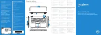 Dell Inspiron 5523 User Manual
 Dell Inspiron 5721 User Manual
 Dell Inspiron 7500 User Manual
 Dell Inspiron 8000 User Manual
 Dell Inspiron 8200 User Manual
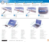 Dell Inspiron 8500 User Manual
 Dell Inspiron 8600 User Manual
 Dell Inspiron 9100 User Manual
 Dell Inspiron M101Z User Manual