Sharp AR-161 - Manuals
Sharp AR-161 Photocopier – Manual, User Manual in PDF format online.
Manuals:
Manual Sharp AR-161


Summary
AR-161 AR-161 Warning!This product is a class A product.If it is operated in households, offices or similar surroundings, itcan produce radio interferences at other appliances, so that theuser has to take adequate countermeasures. CLASS 1 LASER PRODUCT LASER KLASSE 1 LUOKAN 1 LASERLAITE KLASS 1 LASE...
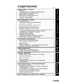
CONTENTS [ 1 ] GENERAL . . . . . . . . . . . . . . . . . . . . . . . . . . . . . . . 1-1 1. General . . . . . . . . . . . . . . . . . . . . . . . . . . . . . . . 1-1 2. Target user copy volume: Monthly average . . . 1-1 3. Main features . . . . . . . . . . . . . . . . . . . . . . . . . . . 1-1 4. Sy...
[3] CONSUMABLE PARTS 1. Supply system table A. USA, CANADA NO Name Content Life Product name of other company Package Remark 1 Developer cartridge (Black) Toner/developer cartridge (Toner 610g, Developer 395g) × 1 15K AR-200TD( * 1 AR-200TD-J) 4 Life setting by A4 6%document Vinyl bag × 1 2 Drum car...
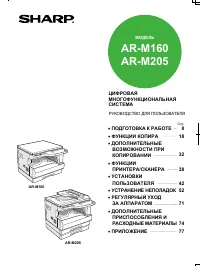
User Manual Sharp AR-161


Summary
1 2 Built-in With optional AR-EB9 16 CPM First copy time 1st. 7.2 sec. ..... 1 5 1 5 1 5 1 5 1 5 Scan Once/Print Many andElectronic Sorting Document isscanned... Multi-pageoriginal stored inmemory... Copies electronically sorted... and stacked offsetduring output. 1,100 Rotation Copy Edge Erase 2-in...
3 4 16 PPM SPLC (Sharp Printer Language with Compression) Printing Compress print data, reduce transfer time Host-based print data Data is compressed Transfer Decompressing Transfer time reduced by nearly half (vs. host-based) Fast printing of text and graphics USB 2.0 (with AR-EB9) USB 1.1 IEEE 128...
5 6 Conventional Memory Transmission Quick On-Line Transmission (AR-M161) Scan All Send Saves Time Scan Call Send Call Job Separator Fax/printer output Copier/printer output Operation Panel The AR-M161’s operation panel is created under a universal design concept, making it easy for everyone to use,...
Sharp Photocopiers Manuals
-
 Sharp AR-151
Manual
Sharp AR-151
Manual
-
 Sharp AR-156
Manual
Sharp AR-156
Manual
-
 Sharp AR-201
User Manual
Sharp AR-201
User Manual
-
Sharp AR-201
Manual
-
 Sharp AR-206
User Manual
Sharp AR-206
User Manual
-
 Sharp AR-235
Manual
Sharp AR-235
Manual
-
 Sharp AR-5015N
User Manual
Sharp AR-5015N
User Manual
-
 Sharp AR-5120
User Manual
Sharp AR-5120
User Manual
-
 Sharp AR-M160
User Manual
Sharp AR-M160
User Manual
-
Sharp AR-M160
Manual
-
 Sharp SF-2530
User Manual
Sharp SF-2530
User Manual
-
 Sharp SF-2040
User Manual
Sharp SF-2040
User Manual
-
 Sharp Z-810
User Manual
Sharp Z-810
User Manual
-
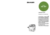 Sharp AR-507
Manual
Sharp AR-507
Manual
-
Sharp AR-507
User Manual
-
 Sharp AR-505
User Manual
Sharp AR-505
User Manual
-
 Sharp AR-5015
User Manual
Sharp AR-5015
User Manual
-
 Sharp AR-405
User Manual
Sharp AR-405
User Manual
-
 Sharp AR-287
Manual
Sharp AR-287
Manual
-
Sharp AR-287
User Manual