Samsung SMO-150TRP - Manuals
Samsung SMO-150TRP Sound Bar – User Manual in PDF format online.
Manuals:
User Manual Samsung SMO-150TRP


Summary
FCC & ICES Information Warning This equipment has been tested and found to comply the limits for a classA digital device, pursuant to part 15 of the FCC Rules and ICES-003 ofIndustry Canada. These limits are designed to provide reasonable protec-tion against harmful interference when the equipme...
Chapter 1: Overview Overview The product is a triplex that enables you to record the signalsreceived from up to 8 cameras to a single VCR. You can record thosesignals sequentially by frame or intermittently, and playback a specif-ic channel selectively. You can use three monitor screen modes, LIVEMo...
Eng-5 I. MENU Display the Setup menu on the screen. Press itagain to exit the Setup menu. J. MULTISCREEN Switches to the split screen view. Each pressof this button changes to the 4, 8, and 9-splitscreen sequentially. Only the 9 and 16 splitscreens are available in the Triplex mode. K. SEQUENCE When...
Samsung Sound Bars Manuals
-
 Samsung HW-A650
User Manual
Samsung HW-A650
User Manual
-
 Samsung HW-B450
User Manual
Samsung HW-B450
User Manual
-
 Samsung HW-B650-XY
User Manual
Samsung HW-B650-XY
User Manual
-
 Samsung HW-C450-XY
User Manual
Samsung HW-C450-XY
User Manual
-
 Samsung HW-Q600C-XY
User Manual
Samsung HW-Q600C-XY
User Manual
-
 Samsung HW-Q700AXY
User Manual
Samsung HW-Q700AXY
User Manual
-
 Samsung HW-Q700C-XY
User Manual
Samsung HW-Q700C-XY
User Manual
-
 Samsung HW-Q800C-XY
User Manual
Samsung HW-Q800C-XY
User Manual
-
 Samsung HW-Q870AXY
User Manual
Samsung HW-Q870AXY
User Manual
-
 Samsung HW-Q930C-XY
User Manual
Samsung HW-Q930C-XY
User Manual
-
 Samsung HW-Q990C-XY
User Manual
Samsung HW-Q990C-XY
User Manual
-
 Samsung HW-S60B-XY
User Manual
Samsung HW-S60B-XY
User Manual
-
 Samsung HW-S61
User Manual
Samsung HW-S61
User Manual
-
 Samsung HW-S61B-XY
User Manual
Samsung HW-S61B-XY
User Manual
-
 Samsung HW-S800B-XY
User Manual
Samsung HW-S800B-XY
User Manual
-
 Samsung HW-S801B-XY
User Manual
Samsung HW-S801B-XY
User Manual
-
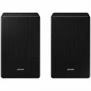
 Samsung SWA-9200SXY
User Manual
Samsung SWA-9200SXY
User Manual
-
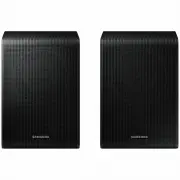
 Samsung SWA-9500SXY
User Manual
Samsung SWA-9500SXY
User Manual
-
 Samsung HW-A430
User Manual
Samsung HW-A430
User Manual
-
 Samsung HW-A440
User Manual
Samsung HW-A440
User Manual