Page 2 - Warning; Warnings
2 3 Important Safety Instructions Safety Precautions E E 1. Read these instructions. 2. Keep these instructions. 3. Heed all warnings. 4. Follow all instructions. 5. Do not use this apparatus near water. 6. Clean only with dry cloth. 7. Do not block any ventilation openings, Install in accordance wi...
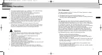
Page 3 - Safety Precautions; Cautions
5 E 4 Safety Precautions E 6. Do not place conductive objects (e.g., screwdrivers, coins, and metal things) or containers filled with water on top of the camera.(Serious injury may result from fire, electrical shock, or falling objects.) 7. Do not install the unit in humid, dusty, or sooty locations...
Page 4 - Table of Contents; Chapter 1
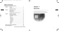
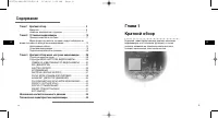
E 7 E 6 Table of Contents Chapter 1 Overview This chapter briefly introduces the Camera and describes its key features, part names and functions. Chapter 1 Overview ........................................................................ 7 Introduction ..................................................
Page 5 - Front View
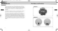
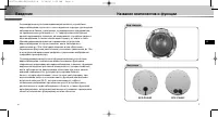
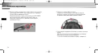
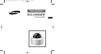
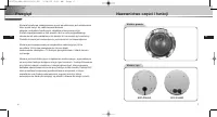
E 9 E 8 Introduction Part Names and Functions The Anti-Vandal Dome Camera is a dome-typed surveillance device thatoffers the best features of surveillance for banks, retail stores, commercialbuildings, industrial settings, and etc. It is designed to withstand intentionalor accidental impact or vanda...
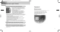
Page 6 - Part Names and Functions; Camera Operation Switches (Setup Switches); In the usual operation mode; Chapter 2; Installing the Camera
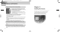
10 11 Part Names and Functions E E ❶ Camera Operation Switches (Setup Switches) The functions of the camera operation switches changedepending on whether the Camera is currently in theusual operation mode (i.e., the setup menu is not showingon the screen) or the setup menu mode. ➻ In the usual opera...
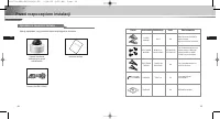
Page 7 - Before Installation; Checking the Contents of the Package; Image
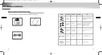
12 13 Before Installation E E Checking the Contents of the Package Be sure to check that the following items are included in the package. Anti-Vandal Dome Camera User’s Guide ALARM & RS485 Cable User’s Guide Image Item Name Standard Quantity Use PLASTIC ANCHOR ASSY SCREW MACHINE ASSY SCREW TAPPI...
Page 9 - Power Adapter Cable
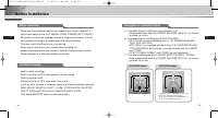
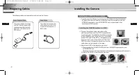
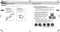
16 17 Preparing Cables E E Installing the Camera The following cables are required to install and use the Camera. Power Adapter Cable Video Cable The power adapter that plugsinto the Camera’s power inputreceptacle has the rated volt-age of DC 12V 600mA or AC24V 300mA. The cable that connects thevide...
Page 10 - Installing the CAMERA side to a PIPE
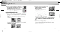
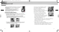
18 19 Installing the Camera E E Installing the CAMERA side to a PIPE 1. Pull the power cable and video cable from the PIPE assembly hole at the bottom of the CAMERA bottom,out through the PIPE assembly holeon the side. 1) Use a coin or slotted driver to turn the CAP BOLT assembled in the PIPE assemb...
Page 11 - Installing on the ceiling
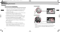
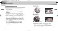
20 21 Installing the Camera E E Installing on the ceiling 1. Carefully read the 'Before Installation' section before starting installation. - All holes that are not used for installation must be closed up with the SCREWs provided in your ACCESSORY set as described in the installation HOLE section. 2...
Page 12 - Additionally Connecting the ALARM CABLE
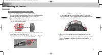
22 23 Installing the Camera E E 1. To connect the ALARM CABLE,disassemble the DOME COVER. (For more information on disassembling the DOME COVER and assemble methods,please refer to 'Installing the CAMERA bottom to a PIPE' in section no. 3.) 2. Disassemble the CAMERA bundle from the CASE. 1) Unscrew ...
Page 13 - Connecting Cables and Checking Operations
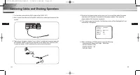
E 25 E 24 Connecting Cables and Checking Operations 1. First connect one end of the BNC cable to the VIDEO OUT. 2. Next, connect the other end of the BNC cable to the video input terminal of the monitor. 3. Then, plug in the power adapter. Use a “minus” screwdriver to connect one part of the power a...
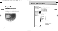
Page 14 - Structure of the Setup Menu; Chapter 3; Setup Menu Overview
E 27 E 26 Structure of the Setup Menu Chapter 3 Setup Menu Overview This chapter looks into the overall organization of the setupmenus and explains their functions. ON.../OFF ALC.../WDR.../MANU... OFF/1/100 ~ 1/10K/AUTO X2~X160 OFF/LOW/HIGH(AGC) S.SLOW/SLOW/NORM/FAST/F.FAST(MOTION) ATW1/ATW2/AWC/MAN...
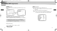
Page 15 - CAMERA MENU Organization; CAMERA ID; ALC; IRIS; BLC
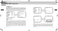
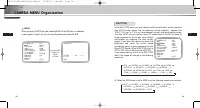
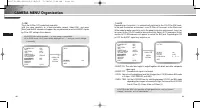
28 29 CAMERA MENU Organization E E CAMERA ID In the CAMERA ID menu, you may designate the CAMERA ID to be displayed in the monitorconnected to a camera. Set the CAMERA ID menu to ON... and press [ENTER] and theCAMERA ID setup submenu will appear. The CAMERA ID may be created by up to 20 digits byusi...
Page 16 - WDR
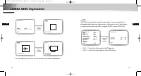
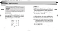
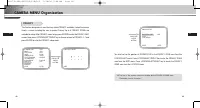
30 31 CAMERA MENU Organization E E Use [Left, Right] key in the LEVEL menu to control the video output level(brightness). PRESS THE ENTER BUTTON. (IRIS/ALC) BLC USER...LEVEL (0) L-----I-----H RET SIZE LOCATION PRESS THE ENTER BUTTON. SIZE LOCATION SIZE LOCATION WDR WDR(Wide Dynamic Range) enlarges t...
Page 17 - MANU; SHUTTER
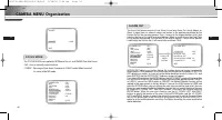
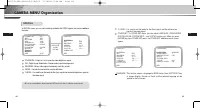
32 33 CAMERA MENU Organization E E MANU When you press [ENTER] key after selecting MANU in the IRIS item, an additional screen appears in which you can set manually opening or closing the IRIS. PRESS THE ENTER BUTTON. CAMERA ID ON... IRIS MANU... SHUTTER OFF AGC LOW WHITE BAL ATW1... FOCUS MODE ONEA...
Page 18 - WHITE BAL
34 35 CAMERA MENU Organization E E In the AGC (Automatic Gain Control) option, you can specify whether toautomatically control the GAIN when the obtained video is below a certain level ofbrightness because it was recorded under insufficient lighting. To automaticallycontrol the GAIN, set the AGC opt...
Page 19 - FOCUS MODE; ALARM SET
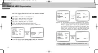
36 37 E E The FOCUS MODE menu performs MF(Manual Focus), and ONEAF(One Auto Focus). - MF : You can manually adjust the focus. - ONEAF : Focusing will take about 5 seconds in ONEAF mode. When turned off, it is same to the MF mode. FOCUS MODE CAMERA ID ON... IRIS ALC... SHUTTER OFF AGC LOW WHITE BAL A...
Page 20 - COLOR
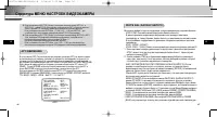
38 39 CAMERA MENU Organization E E ❖ 1. MOTION detection function operates based on the brightness change within the setup region. Therefore, erroneous operation may occur depending on the brightness difference between the background and the object that is being taken, or the status of the area setu...
Page 21 - BW; AUTO
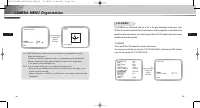
40 41 CAMERA MENU Organization E E BW This is the IR Filter OFF mode, black-and-white (with the same sensitivity as a black-and-white camera). Select BW... and press [Enter] and the BW submenu will appear. You may determine to sent out BURST signalsby ON or OFF setting in this submenu. PRESS THE ENT...
Page 22 - PRIVACY
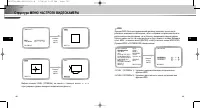
42 CAMERA MENU Organization E 43 E This function designates an area that may violate PRIVACY and hides it when the camera shoots a screen including the area to protect Privacy. Up to 8 PRIVACY ZONEs are available for setup. After PRIVACY menu setup, press ENTER to enter the PRIVACY MAP screen. Now, ...
Page 23 - SPECIAL
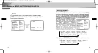
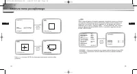
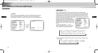
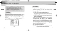
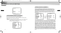
45 E 44 CAMERA MENU Organization E In SPECIAL menu, you can set the settings related to the VIDEO signals and various additionalfunctions. POSI/NEGA : Output as it is or mirror the video brightness signal. DIS : Digital Image Stabilization. Compensates hand shivering errors. REVERSE : Mirrors video ...
Page 25 - PRESET; EXIT
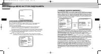
49 E 48 CAMERA MENU Organization E PRESET Select the PRESET menu and press [ENTER] and the PRESET MAP submenu screenwill appear. Select the PRESET number and press [ENTER] and the above screen will appear.- POSITION SET : Memorizes the position of ZOOM or FOCUS.- PRESET ID : Designates the ID on the...
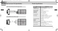
Page 27 - External Connector Pin Specifications; CN 52 : Camera Power Input and Video Signal Output
53 E ITEM DESCRIPTION Product Type Anti-Vandal Dome Camera Power Source Voltage AC 24V ± 10% (NTSC:60Hz ± 0.1Hz, PAL:50Hz ± 0.1Hz), DC12V +10% ~ -5% Power Consumption Approx. 6W Broadcast System NTSC(PAL) Standard Color System Imaging Device 1/4 inch IT S-HAD CCD Effective Pixel NTSC : 768(H) X 494(...
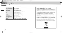
Page 28 - Product Specifications; ITEM
54 E Product Specifications ITEM DESCRIPTION Back Light Compensation Off/On (Area Setting) Sense Up Off/Auto 2x~160x Digital Zoom Off/On(x10), PIP Motion Detection Off/On (Area/Sensitivity Setting) Video Control POSI/NEGA, MIRROR, Detail Setting Signal Output Composite Video Out : 1.0 Vp-p 75 ohms/B...
Page 30 - êÛÍÓ‚Ó‰ÒÚ‚Ó ÔÓÎ ̧ÁÓ‚‡ÚÂÎfl
ÄçíàÇÄçÑÄãúçÄü äìèéãúçÄü ÇàÑÖéäÄåÖêÄ SCC-C9302(F)P êÛÍÓ‚Ó‰ÒÚ‚Ó ÔÓθÁÓ‚‡ÚÂÎfl R 00577A-SCC-C9302(F)P-R 5/18/06 9:56 AM Page 1
Page 31 - LJÊÌ ̊ ԇ‚Ë· ÚÂıÌËÍË ·ÂÁÓÔ‡ÒÌÓÒÚË; è‰ÛÔÂʉÂÌËÂ; è‰ÛÔÂʉÂÌËfl
2 3 R R LJÊÌ˚ ԇ‚Ë· ÚÂıÌËÍË ·ÂÁÓÔ‡ÒÌÓÒÚË è‰ÒÚ‡‚ÎÂÌ̇fl ÌËÊ ËÌÙÓχˆËfl ÒÓ‰ÂÊËÚ Ô‡‚Ë· ÚÂıÌËÍË ·ÂÁÓÔ‡ÒÌÓÒÚË, ÍÓÚÓ˚ ÌÛÊÌÓ Òӷβ‰‡Ú¸ ‰Îfl ÚÓ„Ó, ˜ÚÓ·˚ Ô‡‚ËθÌÓ ËÒÔÓθÁÓ‚‡Ú¸ ‰‡ÌÌÓ ËÁ‰ÂÎËÂ Ë Ô‰ÓÚ‚‡ÚËÚ¸ ÔÓ‚ÂʉÂÌË ÒÓ·ÒÚ‚ÂÌÌÓÒÚË. ëÚÓ„Ó Òӷ≇ÈÚ ‚Ò ԇ‚Ë· ÚÂıÌËÍË ·ÂÁÓÔ‡ÒÌÓÒÚË. ❖ è‰ÒÚ‡‚ÎÂÌ...
Page 32 - ëÓ‰ÂʇÌËÂ; É·‚‡ 1; É·‚‡ 1 ä‡ÚÍËÈ Ó·ÁÓ
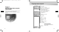
R 5 R 4 ëÓ‰ÂʇÌË É·‚‡ 1 ä‡ÚÍËÈ Ó·ÁÓ Ç ‰‡ÌÌÓÈ „·‚ Ô‰ÒÚ‡‚ÎÂÌÓ Í‡ÚÍÓ ÓÔËÒ‡ÌË‚ˉÂÓ͇ÏÂ˚ Ë Â ÓÒÌÓ‚Ì˚ı ÙÛÌ͈ËÈ, ‡ Ú‡ÍÊÂÛ͇Á‡Ì˚ ̇Á‚‡ÌËfl  ÓÒÌÓ‚Ì˚ı ÍÓÏÔÓÌÂÌÚÓ‚ ËÓÔËÒ‡ÌÓ Ì‡Á̇˜ÂÌË ˝ÚËı ÍÓÏÔÓÌÂÌÚÓ‚. É·‚‡ 1 ä‡ÚÍËÈ Ó·ÁÓ ...........................................................................
Page 33 - Çˉ ÒÔ‰Ë
R 7 R 6 ǂ‰ÂÌË ç‡Á‚‡ÌË ÍÓÏÔÓÌÂÌÚÓ‚ Ë ÙÛÌ͈ËË ÄÌÚË‚‡Ì‰‡Î¸Ì‡fl ÍÛÔÓθ̇fl ‚ˉÂÓ͇χ fl‚ÎflÂÚÒfl ÛÒÚÓÈÒÚ‚ÓςˉÂÓ̇·Î˛‰ÂÌËfl ÍÛÔÓθÌÓ„Ó ÚËÔ‡ Ë Ë‰Â‡Î¸ÌÓ ÔÓ‰ıÓ‰ËÚ ‰Îfl ‚‰ÂÌËfl̇·Î˛‰ÂÌËfl ‚ ·‡Ì͇ı, ‚ χ„‡ÁË̇ı, ̇ ÍÓÏϘÂÒÍËı Ô‰ÔËflÚËflı,̇ ÔÓÏ˚¯ÎÂÌÌ˚ı ÛÒÚ‡Ìӂ͇ı Ë Ú. Ô. 쉇ÓÔӘ̇fl ÍÓÌÒÚÛ͈Ëfl‰‡ÌÌÓÈ ‚ˉ...
Page 34 - ç‡Á‚‡ÌË ÍÓÏÔÓÌÂÌÚÓ‚ Ë ÙÛÌ͈ËË; Ç Ó· ̊ ̃ÌÓÏ ‡·Ó ̃ÂÏ ÂÊËÏÂ; Ç ÂÊËÏ ÏÂÌ ̨ ̇ÒÚÓÂÍ
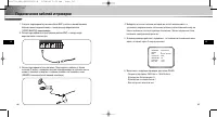
ùÚË ‡Á˙ÂÏ˚ ËÒÔÓθÁÛ˛ÚÒfl ‰Îfl ÔÓ‰Íβ˜ÂÌËfl ͇·ÂÎfl ·ÎÓ͇ ÔËÚ‡ÌËfl Ë͇·ÂÎfl ‚ıÓ‰ÌÓ„Ó ‚ˉÂÓÒ˄̇·. ùÚË ‡Á˙ÂÏ˚ ËÒÔÓθÁÛ˛ÚÒfl ‰Îfl ÔÓ‰Íβ˜ÂÌËfl ͇·ÂÎfl ‰ËÒڇ̈ËÓÌÌÓ„ÓÛÔ‡‚ÎÂÌËfl RS485 Ë Í‡·ÂÎfl,ÍÓÚÓ˚È ËÒÔÓθÁÛÂÚÒfl ‰Îfl Ô‰‡˜Ë ëàÉçÄãÄ íêÖÇéÉà ÔË ‡·ÓÚ ‚ÂÊËÏ ÑÖíÖäíéêÄÑÇàÜÖçàü. 9 R 8 ç‡Á‚‡ÌË ÍÓÏÔÓÌÂÌÚÓ‚ Ë ÙÛ...
Page 35 - É·‚‡ 2; ìÒÚ‡Ìӂ͇ ‚ˉÂÓ͇Ï ̊; èÓ‚Â͇ ÍÓÏÔÎÂÍÚ‡ ÔÓÒÚ‡‚ÍË
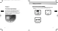
10 R 11 R É·‚‡ 2 ìÒÚ‡Ìӂ͇ ‚ˉÂÓ͇ÏÂ˚ Ç ˝ÚÓÈ „·‚ ÓÔËÒ‡ÌÓ, ͇ÍË ÔÓ‚ÂÍË ‰ÓÎÊÌ˚ ·˚Ú¸‚˚ÔÓÎÌÂÌ˚ Ô‰ ÛÒÚ‡ÌÓ‚ÍÓÈ ‚ˉÂÓ͇ÏÂ˚, Í‡Í ‚˚·‡Ú¸ÏÂÒÚÓ ‰Îfl ÛÒÚ‡ÌÓ‚ÍË ‚ˉÂÓ͇ÏÂ˚, Ë Í‡ÍË ÏÂ˚Ô‰ÓÒÚÓÓÊÌÓÒÚË ÒΉÛÂÚ Òӷβ‰‡Ú¸ ‚Ó ‚ÂÏfl ÛÒÚ‡ÌÓ‚Í˂ˉÂÓ͇ÏÂ˚. íÂÔ¸ ‰‡‚‡ÈÚ ÛÒÚ‡ÌÓ‚ËÏ ‚ˉÂÓ͇ÏÂÛ ËÔÓ‰Íβ˜ËÏ Í ...
Page 36 - àÁÓ·‡ÊÂÌË ç‡Á‚‡ÌË ̋ÎÂÏÂÌÚ‡ ëڇ̉‡Ú; è‰ ÛÒÚ‡ÌÓ‚ÍÓÈ
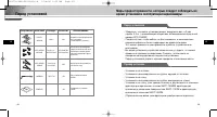
12 13 R R åÂ˚ Ô‰ÓÒÚÓÓÊÌÓÒÚË, ÍÓÚÓ˚ ÒΉÛÂÚ Òӷβ‰‡Ú¸ ‚Ó‚ÂÏfl ÛÒÚ‡ÌÓ‚ÍË Ë ˝ÍÒÔÎÛ‡Ú‡ˆËË ‚ˉÂÓ͇ÏÂ˚ è‰ ÛÒÚ‡ÌÓ‚ÍÓÈ àÁÓ·‡ÊÂÌË ç‡Á‚‡ÌË ˝ÎÂÏÂÌÚ‡ ëڇ̉‡Ú äÓ΢ÂÒÚ‚Ó àÒÔÓθÁÓ‚‡ÌË PLASTIC ANCHOR ASSY SCREW MACHINE ASSY SCREW TAPPING LWRENCH TEMPLATE ÇÒÚ‡‚¸Ú ‚ ÓÚ‚ÂÒÚË ‰Îfl ‚ËÌÚ‡ ‚ÏÂÒÚ ÛÒÚ‡ÌÓ‚...
Page 37 - éÔËÒ‡ÌË ÓÚ‚ÂÒÚËÈ ‰Îfl ÛÒÚ‡ÌÓ‚ÍË
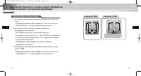
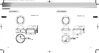
14 15 R R åÂ˚ Ô‰ÓÒÚÓÓÊÌÓÒÚË, ÍÓÚÓ˚ ÒΉÛÂÚ Òӷβ‰‡Ú¸ ‚Ó‚ÂÏfl ÛÒÚ‡ÌÓ‚ÍË Ë ˝ÍÒÔÎÛ‡Ú‡ˆËË ‚ˉÂÓ͇ÏÂ˚ éÔËÒ‡ÌË ÓÚ‚ÂÒÚËÈ ‰Îfl ÛÒÚ‡ÌÓ‚ÍË çËÊÌflfl ˜‡ÒÚ¸ SCC-C9302P çËÊÌflfl ˜‡ÒÚ¸ SCC-C9302F ÑÎfl ‰ÓÔÓÎÌËÚÂθÌÓ„Ó ÔÓ‰Íβ˜ÂÌËfl ͇·ÂÎfl Ò˄̇· ÚÂ‚Ó„Ë ËÁ‚ÎÂÍËÚ ÂÁËÌÓ‚Û˛ Á‡„ÎÛ¯ÍÛ, ÔÓÔÛÒÚËÚ ͇·Âθ ˜ÂÂÁ ˝ÚÓ ÓÚ...
Page 38 - çÂÓ·ıÓ‰ËÏ ̊ ͇·ÂÎË; ìÒ Ú‡Ì Ó‚ Í ‡ ÌËÊÌÂÈ ̃‡ÒÚË Í‡Ï ̊ ̇ ÚÛ·ÍÛ
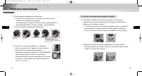
16 17 R R çÂÓ·ıÓ‰ËÏ˚ ͇·ÂÎË ìÒ Ú‡ ÌÓ ‚ Í ‡ ̇ ÚÛ·ÍÛ (‰Îfl SCC-C9302P) 1. ÇÌËχÚÂθÌÓ ÔÓ˜ËÚ‡ÈÚ ‡Á‰ÂÎ "è‰ ÛÒÚ‡ÌÓ‚ÍÓÈ " Ô‰ ̇˜‡ÎÓÏ ‚˚ÔÓÎÌÂÌËfl ÛÒÚ‡ÌÓ‚ÍË.- ÇÒ ÓÚ‚ÂÒÚËfl, ÍÓÚÓ˚ Ì ÔÓÚÂ·Û˛ÚÒfl ‰Îfl ÛÒÚ‡ÌÓ‚ÍË, ‰ÓÎÊÌ˚ ·˚Ú¸ Á‡Í˚Ú˚ ‚ËÌÚ‡ÏË, ÔË·„‡˛˘ËÏËÒfl ‚ ̇·Ó ‡ÍÒÂÒÒÛ‡Ó‚, Í‡Í ÓÔËÒ‡ÌÓ ...
Page 39 - ìÒ Ú‡Ì Ó‚ Í ‡ ·ÓÍÓ‚ÓÈ ̃‡ÒÚË Í‡Ï ̊ ̇ ÚÛ·ÍÛ
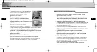
18 19 ìÒÚ‡Ìӂ͇ ‚ˉÂÓ͇ÏÂ˚ R R 3) ìÒÚ‡Ì Ó‚ ËÚ Â ÍÛÔÓθÌÛ˛ Í˚¯ÍÛ. (ë ÔÓÏÓ˘¸˛ „‡Â˜ÌÓ„Ó Íβ˜‡ ÔÎÓÚÌÓ ÔËÍÛÚËÚ ‚ËÌÚ Ì‡ ÏÂÒÚÓ,˜ÚÓ·˚ Ó·ÂÒÔ˜ËÚ¸ ‚Ó‰ÓÌÂÔÓÌˈ‡ÂÏÓÒÚ¸.)- ÑÎfl ËÁÏÂÌÂÌËfl ‡ÒÔÓÎÓÊÂÌËfl ÎÓ„ÓÚËÔ‡ SAMSUNG ̇ ÍÛÔÓθÌÓÈ Í˚¯Í ËÁÏÂÌËÚ ÔÓÎÓÊÂÌËÂÒÓ‰ËÌËÚÂθÌÓÈ ÂÁËÌÓ‚ÓÈ ÔÓÍ·‰ÍË Ë ÛÒÚ‡ÌÓ‚ËÚ ӷ...
Page 41 - ÑÓÔÓÎÌËÚÂÎ ̧ÌÓ ÔÓ‰ÍÎ ̨ ̃ÂÌË ͇·ÂÎfl Ò˄̇· Ú‚ӄË
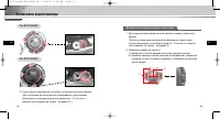
22 ìÒÚ‡Ìӂ͇ ‚ˉÂÓ͇ÏÂ˚ R 23 R For SCC-C9302P For SCC-C9302F 6. éÚ„ÛÎËÛÈÚ ̇ԇ‚ÎÂÌË ӷ˙ÂÍÚË‚‡ Ë ÛÒÚ‡ÌÓ‚ËÚ ÍÛÔÓθÌÛ˛ Í˚¯ÍÛ. (ÑÎfl ÔÓÎÛ˜ÂÌËfl ‰ÓÔÓÎÌËÚÂθÌÓÈ ËÌÙÓχˆËË Ó Â„ÛÎËÓ‚ÍÂÓ·˙ÂÍÚË‚‡ Ë ÛÒÚ‡ÌÓ‚Í ÍÛÔÓθÌÓÈ Í˚¯ÍË ÒÏ. "ìÒ Ú‡Ì Ó‚ Í ‡ÌËÊÌÂÈ ˜‡ÒÚË Í‡ÏÂ˚ ̇ ÚÛ·ÍÛ " ‚ ‡Á‰ÂΠ3.) ÑÓÔ...
Page 43 - èÓ‰ÍÎ ̨ ̃ÂÌË ͇·ÂÎÂÈ Ë ÔÓ‚ÂÍË
R 27 R 26 èÓ‰Íβ˜ÂÌË ͇·ÂÎÂÈ Ë ÔÓ‚ÂÍË 1. ë̇˜‡Î‡ ÔÓ‰ÒÓ‰ËÌËÚ ‡Á˙ÂÏ Í‡·ÂÎfl BNC (͇·Âθ Ò ÏËÌˇڲÌ˚ÏË ·‡ÈÓÌÂÚÌ˚ÏË ÒÓ‰ËÌËÚÂÎflÏË) Í „ÌÂÁ‰Û ‚˚ıÓ‰‡ ‚ˉÂÓÒ˄̇· (VIDEO BõXOÑ) ‚ˉÂÓ͇ÏÂ˚. 2. á‡ÚÂÏ ÔÓ‰ÒÓ‰ËÌËÚ ‚ÚÓÓÈ ‡Á˙ÂÏ Í‡·ÂÎfl BNC Í „ÌÂÁ‰Û ‚ıÓ‰‡ ‚ˉÂÓÒ˄̇· ̇ ÏÓÌËÚÓÂ. 3. á‡ÚÂÏ ÔÓ‰ÒÓ‰ËÌËÚ ·...
Page 44 - ëÚÛÍÚÛ‡ ÏÂÌ ̨ ̇ÒÚÓÂÍ; É·‚‡ 3
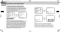
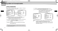
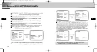
R 29 R 28 ëÚÛÍÚÛ‡ ÏÂÌ˛ ̇ÒÚÓÂÍ É·‚‡ 3 ä‡ÚÍËÈ Ó·ÁÓ ÏÂÌ˛ ̇ÒÚÓÂ͂ˉÂÓ͇ÏÂ˚ Ç ‰‡ÌÌÓÈ „·‚ ÛÍÓ‚Ó‰ÒÚ‚‡ ÓÔË҇̇ Ó·˘‡flÓ„‡ÌËÁ‡ˆËfl ÏÂÌ˛ ̇ÒÚÓÂÍ ‚ˉÂÓ͇ÏÂ˚, Ë ÓÔËÒ‡Ì˚ ËıÙÛÌ͈ËË. Bäã.../Bõäã ALC.../WDR.../êìóçéâ... Bõäã/1/100 ~ 1/10K/ABTO X2~X160 Bõäã/Hàáäàâ/BõCOäàâ(APì) Oó.MEÑã./MEÑã./HOPM./ÅõCTP...
Page 45 - ëÚÛÍÚÛ‡ åÖçû çÄëíêéÖä ÇàÑÖéäÄåÖêõ
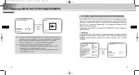
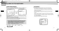
30 31 R R ëÚÛÍÚÛ‡ åÖçû çÄëíêéÖä ÇàÑÖéäÄåÖêõ CAMERA ID (àÑÖçíàîàäÄíéê ÇàÑÖéäÄåÖêõ) åÂÌ˛ ID äAMEPõ ËÒÔÓθÁÛÂÚÒfl ‰Îfl ̇Á̇˜ÂÌËfl ‚ˉÂÓ͇Ï ˉÂÌÚËÙË͇ÚÓ‡, ÍÓÚÓ˚È ÓÚÓ·‡Ê‡ÂÚÒfl ̇ ˝Í‡Ì ÔÓ‰Íβ˜ÂÌÌÓ„Ó Í ‚ˉÂÓ͇Ï ÏÓÌËÚÓ‡. Ç˚·ÂËÚ ‚ ÏÂÌ˛ ‰Îfl ÔÛÌÍÚ‡ ID äAMEPõ ÓÔˆË˛ ON... (Çäã.) Ë Ì‡ÊÏËÚ ÍÌÓÔÍÛ [EN...
Page 47 - êìóçéâ
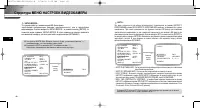
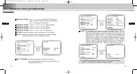
34 35 ëÚÛÍÚÛ‡ åÖçû çÄëíêéÖä ÇàÑÖéäÄåÖêõ R R êìóçéâ ÖÒÎË ÔÓÒΠ‚˚·Ó‡ ÔÛÌÍÚ‡ êìóçéâ ‚ ÏÂÌ˛ ÑàÄîêÄÉåÄ Ì‡Ê‡Ú¸ Í·‚˯Û[ENTER], ÔÓfl‚ËÚÒfl ‰ÓÔÓÎÌËÚÂθÌ˚È ˝Í‡Ì, ‚ ÍÓÚÓÓÏ ÏÓÊÌÓ ‚Û˜ÌÛ˛ ̇ÒÚÓËÚ¸‡ÒÍ˚ÚË Á‡Í˚ÚË ‰Ë‡Ù‡„Ï˚. LJÊÏËÚ ÍÌÓÔÍÛ ENTER ID äAMEPõ Bäã... ÑàÄîêÄÉåÄ êìóç... áÄíÇéê Bõäã APì Hàáäàâ ÅÄ...
Page 50 - ñBETHOE
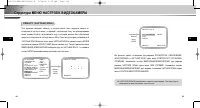
41 R 40 ëÚÛÍÚÛ‡ åÖçû çÄëíêéÖä ÇàÑÖéäÄåÖêõ R ❖ 1. îÛÌ͈Ëfl ‰ÂÚÂÍÚÓ‡ ‰‚ËÊÂÌËfl ‡·ÓÚ‡ÂÚ Ì‡ ÓÒÌÓ‚Â ËÁÏÂÌÂÌËfl flÍÓÒÚË ‚ ԉ·ı ӷ·ÒÚË Ì‡ÒÚÓÈÍË . èÓ˝ÚÓÏÛ ‚ Á‡‚ËÒËÏÓÒÚË ÓÚ ‡Á΢ÌÓÈflÍÓÒÚË ÏÂÊ‰Û ÒÌËχÂÏ˚Ï Ó·˙ÂÍÚÓÏ Ë ÙÓÌÓÏ ËÎË ÒÓÒÚÓflÌËÂÏӷ·ÒÚË Ì‡ÒÚÓÈÍË Ë Ú .‰ ., ‚ÓÁÏÓÊ̇ ÌÂÔ‡‚Ëθ̇fl ‡·ÓÚ‡. ❖ 2. Ç ...
Page 57 - CN 52: ÇıÓ‰ ÔËÚ‡ÌËfl ͇Ï ̊ Ë ‚ ̊ıÓ‰ ‚ˉÂÓÒ˄̇·; ïÄêÄäíÖêàëíàäÄ
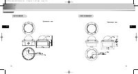
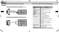
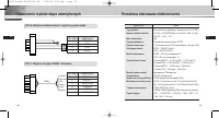
55 R 54 ç‡Á̇˜ÂÌËfl ÍÓÌÚ‡ÍÚÓ‚ ‚̯ÌÂ„Ó ‡Á˙Âχ íÂıÌ˘ÂÒÍË ı‡‡ÍÚÂËÒÚËÍË ‚ˉÂÓ͇ÏÂ˚ R CN 52: ÇıÓ‰ ÔËÚ‡ÌËfl ͇ÏÂ˚ Ë ‚˚ıÓ‰ ‚ˉÂÓÒ˄̇· CN 51: ìÔ‡‚ÎÂÌË ˜ÂÂÁ ËÌÚÂÙÂÈÒ RS485 Ë ‚˚ıÓ‰ Ò˄̇· ÚÂ‚Ó„Ë N º ÍÓÌÚ‡ÍÚ‡ ç‡Á̇˜ÂÌË ÍÓÌÚ‡ÍÚ‡ 1 VBS_BõXOÑ 2 GND 3 AC24- 4 AC24+ N º ÍÓÌÚ‡ÍÚ‡ ç‡Á̇˜ÂÌË ÍÓÌÚ‡ÍÚ‡ 1...
Page 58 - íÂıÌË ̃ÂÒÍË ı‡‡ÍÚÂËÒÚËÍË ‚ˉÂÓ͇Ï ̊; ÑˇԇÁÓÌ ‡·Ó ̃Ëı ÚÂÏÔ‡ÚÛ; 臂ËÎ ̧̇fl Ôӈ‰ۇ ÛÚËÎËÁ‡ˆËË ̋ÚÓ„Ó ËÁ‰ÂÎËfl
R 56 íÂıÌ˘ÂÒÍË ı‡‡ÍÚÂËÒÚËÍË ‚ˉÂÓ͇ÏÂ˚ ïÄêÄäíÖêàëíàäÄ áçÄóÖçàÖ åËÌËχθ̇fl ÓÒ‚Â˘ÂÌÌÓÒÚ¸ ñBETHOE : 0.2 βÍÒ (·ÂÁ ÔÓ‚˚¯ÂÌËfl x4) / 0.005 βÍÒ (·ÂÁ ÔÓ‚˚¯ÂÌËfl X160) ÒˆÂÌ˚ ó-Å : 0.02 βÍÒ (·ÂÁ ÔÓ‚˚¯ÂÌËfl x4) / 0.0005 βÍÒ (·ÂÁ ÔÓ‚˚¯ÂÌËfl X160) ñ‚ÂÚÓ‚‡fl ÚÂÏÔ‡ÚÛ‡ êÂÊËÏ˚ ATW/AWC/PìóHOâ(3200 K, 5600 K, ...
Page 60 - Instrukcja obs∏ugi
KOPU¸KA ZABEZPIECZONA PRZED WANDALIZMEM SCC-C9302(F)P Instrukcja obs∏ugi PL 00577A-SCC-C9302(F)P-PL 5/18/06 9:55 AM Page 1
Page 61 - Instrukcje bezpieczeƒstwa; Ostrze ̋enie; Ostrze ̋enia; Uwaga
2 3 Instrukcje bezpieczeƒstwa PL PL Przeznaczeniem instrukcji na temat bezpieczeƒstwa jest ochrona przedprzypadkowym zranieniem lub uszkodzeniem sprz´tu. Zawszeprzestrzegaj wszystkich instrukcji bezpieczeƒstwa. ❖ Instrukcje bezpieczeƒstwa sà podzielone na “Ostrze˝enia” i “Uwagi” wsposób odznaczony s...
Page 62 - Spis treÊci; Rozdzia∏ 1
PL 5 PL 4 Spis treÊci Rozdzia∏ 1 konfiguracji Ten rozdzia∏ zawiera krótki opis kamery, jej podstawowych funkcji, nazw cz´Êci i funkcji. Chapter 1 konfiguracji .................................................................... 5 Przeglàd ................................................................
Page 63 - Widok z przodu
PL 7 PL 6 Przeglàd Nazewnictwo cz´Êci i funkcji Kamera kopu∏kowa zabezpieczona przed wandalizmem jest urzàdzeniem,które mo˝e s∏u˝yç do nadzorowania banków,sklepów, budynków handlowych, obiektów przemys∏owych itp. Zosta∏a zaprojektowana w taki sposób, aby w razie przypadkowegouderzenia lub aktu wanda...
Page 64 - Nazewnictwo cz ́Êci i funkcji; Przyciski sterowania kamery (przyciski konfiguracji); Normalny tryb pracy; Rozdzia∏ 2; Monta ̋ kamery
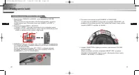
8 9 Nazewnictwo cz´Êci i funkcji PL PL ❶ Przyciski sterowania kamery (przyciski konfiguracji) Funkcje przycisków sterowania kamery zmieniajà si´ w zale˝noÊci od tego, czy kamera dzia∏a w trybie normalnym (tzn. menu konfiguracji nie jest wyÊwietlanena ekranie) czy w trybie konfiguracji. ➻ Normalny tr...
Page 65 - Przed rozpocz ́ciem instalacji; Sprawdzenie zawartoÊci zestawu; Obraz
10 11 Przed rozpocz´ciem instalacji PL PL Sprawdzenie zawartoÊci zestawu Nale˝y sprawdziç, czy poni˝sze cz´Êci znajdujà si´ w zestawie. Kamera kopu∏kowa zabezpieczona przed wandalizmem Instrukcja obs∏ugi Przewód ALARM i RS485 User’s Guide Obraz Nazwa elementu Standardowy IloÊç Zastosowanie PLASTIC A...
Page 66 - Przed zamontowaniem
12 13 Przed rozpocz´ciem instalacji PL PL Przed zamontowaniem Przyk∏ad monta˝u - Sprawdziç, czy miejsce monta˝u mo˝e wytrzymaç obcià˝enie 5-krotnie wi´ksze (oko∏o 5,5 kg) ni˝waga KAMERY KOPU¸KOWEJZABEZPIECZONEJ PRZED WANDALIZMEM (SCC-C9302P). - Zachowaç ostro˝noÊç, aby podczas monta˝u przewód nie zo...
Page 67 - Przewód zasilacza; Mocowanie dolnej cz ́Êci KAMERY na RURZE
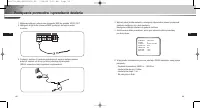
14 15 Przygotowanie kabli PL PL Pod∏àczenie kabli Do zamontowania kamery potrzebne sà nast´pujàce przewody: Przewód zasilacza Przewód wideo Parametry znamionowe zasilacza pod∏àczanego dogniazda zasilania kamery sànast´pujàce: 12 VDC, 600mA lub 24 VAC, 300 mA. Przewód∏àczàcy wyjÊciewideo kamery z mon...
Page 68 - Pod∏àczenie kabli; Mocowanie boku KAMERY na RURZE
16 17 Pod∏àczenie kabli PL PL Mocowanie boku KAMERY na RURZE 1. Wyciàgnàç przewód zasilania i przewód wideo z otworu zespo∏u do mocowania na RURZE u do∏u kamery i przeciàgnàç przez otwór z bokuzespo∏u do mocowania na RURZE. 1) Za pomocà monety lub p∏askiego Êrubokr´ta obróciç ÂRUB¢ z PODK¸ADKÑ zamon...
Page 70 - Dodatkowe pod∏àczanie PRZEWODU ALARMOWEGO
20 21 Pod∏àczenie kabli PL PL 1. Aby pod ∏à czyç PRZEWÓD ALARMOWY, nale˝y zdemontowaç OS¸ON¢ KOPU¸KOWÑ. (Wi´cej informacji na temat demonta˝u OS¸ONY KOPU¸KOWEJ i sposobów monta˝u zawiera cz´Êç „Mocowanie dolnej cz´Êci KAMERY na RURZE” w rozdziale 3.) 2. Wymontowaç zespó∏ KAMERY z OBUDOWY. 1) Odkr´ci...
Page 71 - Pod∏àczanie przewodów i sprawdzanie dzia∏ania
PL 23 PL 22 Pod∏àczanie przewodów i sprawdzanie dzia∏ania 1. Najpierw pod∏àczyç jeden koniec przewodu BNC do gniazda VIDEO OUT.2. Nast´pnie drugi koniec przewodu BNC pod∏àczyç do wejÊcia wideo monitora. 3. Pod∏àczyç zasilacz. Za pomocà Êrubokr´ta do wejÊcia zasilania kamery po∏àczyç zasilacz od stro...
Page 72 - Nawigacja menu poczàtkowego Setup Menu; Rozdzia∏ 3; Przeglàd menu konfiguracji
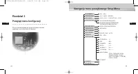
PL 25 PL 24 Nawigacja menu poczàtkowego Setup Menu Rozdzia∏ 3 Przeglàd menu konfiguracji W tym rozdziale znajdujà si´ ogólne informacje na tematorganizacji oraz funkcji menu konfiguracji. WL..../WYL. ALC.../WDR.../RECZNY... WYL./1/100 ~ 1/10K/AUTO X2 ~ X160 WYL./NISKI/WYSOKI(AGC) B.WOLNO/WOLNO/NORMA...
Page 73 - Struktura menu poczàtkowego
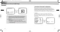
26 27 Struktura menu poczàtkowego PL PL Numer identyfikacyjny kamery (CAMERA ID) W menu ID KAMERY mo˝na w∏àczyç pokazywanie ID kamery na ekraniemonitora pod∏àczonego do tej kamery. Ustaw ID KAMERY w ustawieniuw∏àczonym (ON)... i wciÊnij [ENTER], a wyÊwietli si´ submenu ustawieƒ ID KAMERY. Numer iden...
Page 75 - RECZNY; MIGAWKA
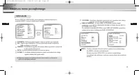
30 31 Struktura menu poczàtkowego PL PL RECZNY JeÊli po wybraniu opcji RECZNY w obszarze PRZYSLONA naciÊni´tyzostanie przycisk [ENTER], wyÊwietlony zostanie ekran dodatkowyumo˝liwiajàcy ustawienie r´cznego otwierania lub zamykania przes∏ony. WCIÊNIJ PRZYCISK ENTER. ID KAMERY WL.... PRZYSLONA RECZNY....
Page 76 - BALANS BIELI
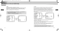
32 33 Struktura menu poczàtkowego PL PL W opcji AGC (Automatycznej optymalizacji obrazu) mo˝na zdecydowaç czy chcesz automatycznie kontrolowaç jakoÊç obrazu kiedy uzyskany obraz ma jasnoÊç na ni˝szym ni˝ po˝àdanym poziomie jasnoÊci z powodu niewystarczajàcej iloÊci Êwiat∏a. Aby automatycznie kontrol...
Page 78 - KOLOR
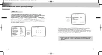
36 37 Struktura menu poczàtkowego PL PL ❖ 1. Funkcja detekcji ruchu dzia∏a na zasadzie zmiany jasnoÊci w ustawionym obszarze. Z tego powodu funkcja mo˝e dzia∏aç wnieprawid∏owy sposób na skutek ró˝nicy jasno Êcipomi´ dzyt∏em a rejestrowanym obiektem lub statusem konfiguracjiobszaru itd. ❖ 2. W kamerz...
Page 81 - SPECJALNE; INNE USTAWIENIA
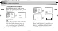
43 PL 42 Struktura menu poczàtkowego PL W menu SPECIAL (SPECJALNE) mo˝na dokonaç ustawieƒ zwiàzanych zsygna∏ami WIDEO i ró˝nymi dodatkowymi funkcjami. POSI/NEGA : Wybór wysy∏ania sygna∏u obrazu w postaci jego negatywu. DIS : Digital Image Stabilization. Cyfrowa stabilizacja obrazu kompensujeb∏´dy wy...
Page 83 - Ustawienia czasu przywrócenia pozycji (HOME RETURN); WYJSCIE
47 PL 46 Struktura menu poczàtkowego PL PRESET Wybierz menu programowania ustawieƒ PRESET i wciÊnij [ENTER],wtedy na ekranie pojawi si´ submenu MAPA PRESETU. Wybierz numer zaprogramowanego ustawienia PRESET NO i wciÊnij[ENTER], wtedy pojawi si´ powy˝sze wskazanie na ekranie.- POSITION SET : Zapami´t...
Page 85 - CN 52: WejÊcie zasilania kamery i wyjÊcie sygna∏u wideo; Nr styku objaÊnienie
51 PL POZYCJA OPIS Typ produktu Kolorowa kamera z wbudowanym obiektywem zoom (TYP NTSC) Napi´cie êród∏a zasilania AC 24V ± 10% (NTSC:60Hz ± 0.1Hz, PAL : 50Hz ± 0.1Hz), DC12V ± 10% ~ -5% Moc znamionowa 6W System nadawania Standardowy system koloru NTSC Element obrazujàcy 1/4-calowa matryca CCD kompat...
Page 86 - Przes∏ona sterowana elektronicznie; POZYCJA; Prawid∏owe pozbywanie si ́ zu ̋ytego produktu
52 PL Przes∏ona sterowana elektronicznie POZYCJA OPIS Kompensacja oÊwietlenia wy wy∏./w∏. (ustawianie obszaru) Czu∏oÊç wy∏./automatyczna 2x ~ 160x Zoom cyfrowy wy∏./w∏.(x10), obraz w obrazie Detekcja ruchu wy∏./w∏. (ustawianie obszaru/czu∏oÊci) Sterowanie wideo POZY./NEGA., LUSTRO, szczegó∏y Sygna∏ ...


 Samsung HW-A650
User Manual
Samsung HW-A650
User Manual
 Samsung HW-B450
User Manual
Samsung HW-B450
User Manual
 Samsung HW-B650-XY
User Manual
Samsung HW-B650-XY
User Manual
 Samsung HW-C450-XY
User Manual
Samsung HW-C450-XY
User Manual
 Samsung HW-Q600C-XY
User Manual
Samsung HW-Q600C-XY
User Manual
 Samsung HW-Q700AXY
User Manual
Samsung HW-Q700AXY
User Manual
 Samsung HW-Q700C-XY
User Manual
Samsung HW-Q700C-XY
User Manual
 Samsung HW-Q800C-XY
User Manual
Samsung HW-Q800C-XY
User Manual
 Samsung HW-Q870AXY
User Manual
Samsung HW-Q870AXY
User Manual
 Samsung HW-Q930C-XY
User Manual
Samsung HW-Q930C-XY
User Manual
 Samsung HW-Q990C-XY
User Manual
Samsung HW-Q990C-XY
User Manual
 Samsung HW-S60B-XY
User Manual
Samsung HW-S60B-XY
User Manual
 Samsung HW-S61
User Manual
Samsung HW-S61
User Manual
 Samsung HW-S61B-XY
User Manual
Samsung HW-S61B-XY
User Manual
 Samsung HW-S800B-XY
User Manual
Samsung HW-S800B-XY
User Manual
 Samsung HW-S801B-XY
User Manual
Samsung HW-S801B-XY
User Manual
 Samsung SWA-9200SXY
User Manual
Samsung SWA-9200SXY
User Manual
 Samsung SWA-9500SXY
User Manual
Samsung SWA-9500SXY
User Manual
 Samsung HW-A430
User Manual
Samsung HW-A430
User Manual
 Samsung HW-A440
User Manual
Samsung HW-A440
User Manual