MSI MEG X570 - Manuals
User Manual MSI MEG X570
1
2
3
4
5
6
7
8
9
10
11
12

13
14
15
16
17
18
19
20
21
22

23
24
25
26
27
28
29
30
31
32
33
34
35
36
37
38

39
40
41
42
43
44
45
46
47
48
49
50
51
52
53
54
55
56
57
58
59

60
61
62
63
64
65
66
67
68
69
70
71
72
73
74
75
76

77
78
79
80
81
82
83
84
85
86
87
88
89
90
91
92
93
94
95
96
97
98
99
100
101
102
103
104
105
106
107
108
109
110
111
112
113
114
115
116
117
118
119
120
121
122
123
124
125
126
127
128
129
130
131
132

133
134
135
136
137
138
139
140
141
142
143
144
145
146
147
148
149
150
151
152
153
154
155
156
157
158
159
160
161
162
163
164
165
166
167
168
169
170
171
172
173
174
175

176
177
178
179
180
181
182
183
184
185
186
187
188
189
190
191
192
193
194
195
196
197
198
199
200
201
202
203
204
205
206
207
208
209
210
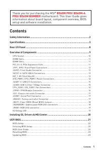
Summary
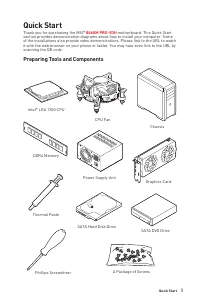
Page 2 - II; Youtube; processeur/ Установка процессора
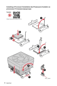
II Quick Start 1 2 3 6 4 5 7 8 9 Youtube https://youtu.be/Xv89nhFk1vc CPU_FAN1 Installing a Processor/ Installation des Prozessors/ Installer un processeur/ Установка процессора
Page 3 - III; Important
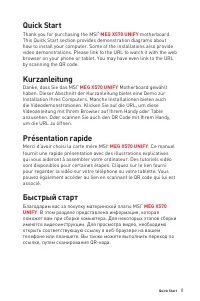
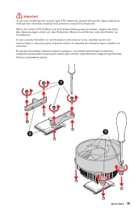
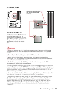
III Quick Start ⚠ Important If you are installing the screw-type CPU heatsink, please follow the figure below to remove the retention module first and then install the heatsink.Wenn Sie einen CPU-Kühler mit Schraubenbefestigung einsetzen, folgen Sie bitte den Anweisungen unten um das Retention-Modul...
Page 4 - IV; Installer une mémoire DDR4/ Установка памяти DDR4
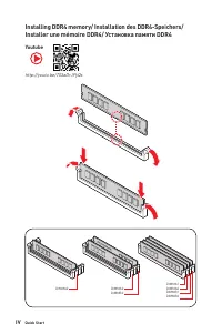
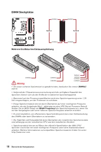
IV Quick Start http://youtu.be/T03aDrJPyQs Youtube DIMMA2 DIMMA2 DIMMB2 DIMMA1 DIMMA2 DIMMB1 DIMMB2 Installing DDR4 memory/ Installation des DDR4-Speichers/ Installer une mémoire DDR4/ Установка памяти DDR4
MSI Motherboards Manuals
-
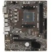
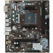
 MSI A320M-A PRO
User Manual
MSI A320M-A PRO
User Manual
-
 MSI A520
User Manual
MSI A520
User Manual
-
 MSI A520M-A PRO
User Manual
MSI A520M-A PRO
User Manual
-
 MSI B450M-A PRO
User Manual
MSI B450M-A PRO
User Manual
-
 MSI B460
User Manual
MSI B460
User Manual
-
 MSI B550-A PRO
User Manual
MSI B550-A PRO
User Manual
-
 MSI B550M PRO-VDH
User Manual
MSI B550M PRO-VDH
User Manual
-
 MSI B560
User Manual
MSI B560
User Manual
-
 MSI B560-A PRO
User Manual
MSI B560-A PRO
User Manual
-
 MSI B560M BOMBER
User Manual
MSI B560M BOMBER
User Manual
-
 MSI B560M PRO-E
User Manual
MSI B560M PRO-E
User Manual
-
 MSI B660
User Manual
MSI B660
User Manual
-
 MSI B660M
User Manual
MSI B660M
User Manual
-
 MSI H510
User Manual
MSI H510
User Manual
-
 MSI H510M-A PRO
User Manual
MSI H510M-A PRO
User Manual
-
 MSI H610
User Manual
MSI H610
User Manual
-
 MSI MAG B550
User Manual
MSI MAG B550
User Manual
-
 MSI MAG B550M
User Manual
MSI MAG B550M
User Manual
-
 MSI MAG B650M
User Manual
MSI MAG B650M
User Manual
-
 MSI MAG Z59
User Manual
MSI MAG Z59
User Manual