Page 2 - II; processeur/ Установка процессора
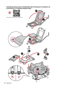
II Quick Start Installing a Processor/ Installation des Prozessors/ Installer un processeur/ Установка процессора ⚽ https://youtu.be/4ce91YC3Oww 1 2 3 6 4 5 7 8 9
Page 3 - III; Installer une mémoire DDR4/ Установка памяти DDR4
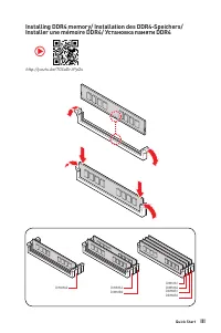
III Quick Start Installing DDR4 memory/ Installation des DDR4-Speichers/ Installer une mémoire DDR4/ Установка памяти DDR4 http://youtu.be/T03aDrJPyQs ⚽ DIMMA2 DIMMA2 DIMMB2 DIMMA1 DIMMA2 DIMMB1 DIMMB2
Page 4 - IV; Connecting the Front Panel Header/ Anschließen der; HDD LED
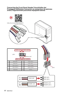
IV Quick Start Connecting the Front Panel Header/ Anschließen der Frontpanel-Stiftleiste/ Connecter un connecteur du panneau avant/ Подключение разъемов передней панели http://youtu.be/DPELIdVNZUI HDD LED RESET SW JFP1 HDD LED HDD LED - HDD LED + POWER LED - POWER LED + POWER LED 1 2 10 9 + + + - - ...
Page 5 - Installing the Motherboard/ Installation des Motherboards/; Youtube
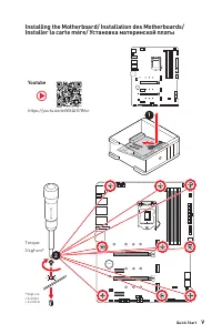
V Quick Start Installing the Motherboard/ Installation des Motherboards/ Installer la carte mère/ Установка материнской платы https://youtu.be/wWI6Qt51Wnc ⚽ Youtube 1 BAT1 2 Torque:3 kgf·cm* *3 kgf·cm = 0.3 N·m = 2.6 lbf·in
Page 6 - Connecting the Power Connectors/ Stromanschlüsse
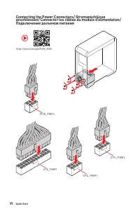
VI Quick Start http://youtu.be/gkDYyR_83I4 ⚽ Connecting the Power Connectors/ Stromanschlüsse anschliessen/ Connecter les câbles du module d’alimentation/ Подключение разъемов питания ATX_PWR1 CPU_PWR1 CPU_PWR2 PCIE_PWR1
Page 7 - VII; Installer le disque dur SATA/ Установка дисков SATA
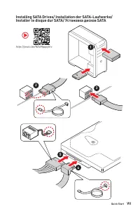
VII Quick Start Installing SATA Drives/ Installation der SATA-Laufwerke/ Installer le disque dur SATA/ Установка дисков SATA http://youtu.be/RZsMpqxythc 1 2 3 4 5 ⚽
Page 8 - VIII; Installing a Graphics Card/ Einbau der Grafikkarte/ Installer
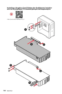
VIII Quick Start 1 http://youtu.be/mG0GZpr9w_A 2 3 4 5 6 Installing a Graphics Card/ Einbau der Grafikkarte/ Installer une carte graphique/ Установка дискретной видеокарты ⚽
Page 9 - IX; Connecting Peripheral Devices/ Peripheriegeräte/ Connecter; MAG Z590 TOMAHAWK WIFI
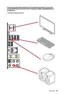
IX Quick Start Connecting Peripheral Devices/ Peripheriegeräte/ Connecter un périphérique anschliessen/ Подключение периферийных устройств ∙ MAG Z590 TOMAHAWK WIFI
Page 11 - XI; питания
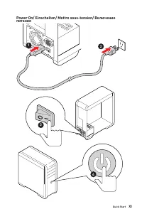
XI Quick Start 4 3 1 2 Power On/ Einschalten/ Mettre sous-tension/ Включение питания
Page 12 - NOTE
Page 13 - Contents; Case stand-off notification
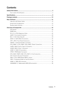
1 Contents Contents Safety Information ................................................................................................. 3 Case stand-off notification ..................................................................................... 4 Specifications .................................
Page 15 - Safety Information
3 Safety Information Safety Information ∙ The components included in this package are prone to damage from electrostatic discharge (ESD). Please adhere to the following instructions to ensure successful computer assembly. ∙ Ensure that all components are securely connected. Loose connections may cau...
Page 16 - serve as a warning to user.
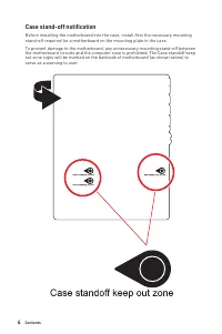
4 Contents Case stand-off notification Before installing the motherboard into the case, install first the necessary mounting stand-off required for a motherboard on the mounting plate in the case. To prevent damage to the motherboard, any unnecessary mounting stand-off between the motherboard circui...
Page 17 - Specifications; CPU; Supports Dual-Channel mode; Expansion Slot; Supports 2-Way AMD® CrossFireTM Technology
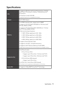
5 Specifications Specifications CPU ∙ Supports 10th Gen Intel® Core™ Processors, 11th Gen Intel® Core™ Processors, Pentium® Gold and Celeron® Processors* ∙ Processor socket LGA1200 * Please go to intel.com for compatibility information. Chipset Intel® Z590 Chipset Memory ∙ 4x DDR4 memory slots, supp...
Page 18 - Onboard Graphics; x USB3.2 Gen2x2 20Gbps Type-C port on the back
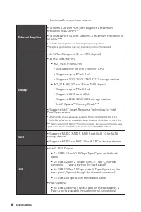
6 Specifications Continued from previous column Onboard Graphics ∙ 1x HDMI 2.0b with HDR port, supports a maximum resolution of 4K 60Hz*/** ∙ 1x DisplayPort 1.4 port, supports a maximum resolution of 4K 60Hz*/** * Available only on processors featuring integrated graphics.** Graphics specifications ...
Page 19 - Continued from previous column; Audio; Supports S/PDIF output; LAN; slot
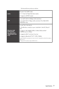
7 Specifications Continued from previous column Audio Realtek® ALC4080 Codec ∙ 7.1-Channel High Definition Audio ∙ Supports S/PDIF output LAN ∙ 1x Intel® I225-V 2.5Gbps LAN controller ∙ 1x Intel® I219-V 1Gbps LAN controller (For MAG Z590 TORPEDO only) Wireless LAN & Bluetooth® (For MAG Z590 TOMA...
Page 20 - Internal Connectors
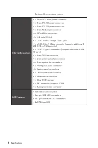
8 Specifications Continued from previous column Internal Connectors ∙ 1x 24-pin ATX main power connector ∙ 1x 8-pin ATX 12V power connector ∙ 1x 4-pin ATX 12V power connector ∙ 1x 6-pin PCIE power connector ∙ 6x SATA 6Gb/s connectors ∙ 3x M.2 slots (M-Key) ∙ 1x USB 3.2 Gen 2 10Gbps Type-C port ∙ 1x ...
Page 21 - Back Panel; x Wi-Fi Antenna connectors (For MAG Z590 TOMAHAWK; Hardware Monitor
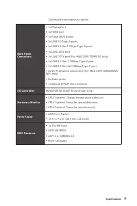
9 Specifications Continued from previous column Back Panel Connectors ∙ 1x DisplayPort ∙ 1x HDMI port ∙ 1x Flash BIOS button ∙ 2x USB 2.0 Type-A ports ∙ 4x USB 3.2 Gen1 5Gbps Type-A ports ∙ 1x LAN I225V port ∙ 1x LAN I219V port (For MAG Z590 TORPEDO only) ∙ 1x USB 3.2 Gen 2 10Gbps Type-A port ∙ 1x U...
Page 22 - Software
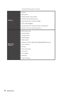
10 Specifications Continued from previous column Software ∙ Drivers ∙ MSI Center ∙ Intel Extreme Tuning Utility ∙ MSI APP Player (BlueStacks) ∙ Open Broadcaster Software (OBS) ∙ CPU-Z MSI GAMING ∙ Google Chrome™, Google Toolbar, Google Drive ∙ Norton™ Internet Security Solution MSI Center Features ∙...
Page 23 - Special Features
11 Specifications Continued from previous column Special Features ∙ Audio ▪ Audio Boost 5 ▪ Sound Tune ∙ Network ▪ 2.5G LAN ▪ LAN Manager ▪ Intel Wi-Fi (For MAG Z590 TOMAHAWK WIFI only) ∙ Cooling ▪ Extended Heatsink Design ▪ M.2 Shield Frozr ▪ Pump Fan ▪ Smart Fan Control ▪ K7 thermal pad ▪ Choke pa...
Page 24 - Multi GPU-CrossFire Technology
12 Specifications Continued from previous column Special Features ∙ Performance ▪ Multi GPU-CrossFire Technology ▪ DDR4 Boost ▪ Core Boost ▪ GAME Boost ▪ Lightning USB 20G ▪ USB 3.2 Gen 2 10G ▪ USB with Type A+C ▪ Front USB Type-C ▪ Dual CPU Power ▪ Lightning Gen 4 PCI-E Slot ▪ Lightning Gen 4 M.2 ▪...
Page 25 - Package contents; Motherboard; Wi-Fi antenna (For MAG Z590 TOMAHAWK WIFI; Important
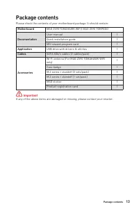
13 Package contents Package contents Please check the contents of your motherboard package. It should contain: Motherboard MAG Z590 TOMAHAWK WIFI/ MAG Z590 TORPEDO Documentation User manual 1 Quick installation guide 1 MSI reward program card 1 Application USB drive with drivers & utilities 1 Ca...
Page 26 - - Please refer to page 41 for Updating BIOS with Flash
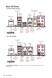
14 Rear I/O Panel Rear I/O Panel ∙ MAG Z590 TOMAHAWK WIFI ∙ Flash BIOS Port/ Button - Please refer to page 41 for Updating BIOS with Flash BIOS Button. USB 3.2 Gen 2x2 (20Gbps) Type-C USB 3.2 Gen 2x2 (20Gbps) Type-C Flash BIOS Button Flash BIOS Button 2.5Gbps LAN 2.5Gbps LAN 1Gbps LAN Wi-Fi Antenna ...
Page 27 - Audio Ports Configuration; Audio Ports; LAN Port LED Status Table; Description; Realtek Audio Console; better sound experience.
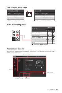
15 Rear I/O Panel Audio Ports Configuration Audio Ports Channel 2 4 6 8 Center/ Sub-woofer Out ● ● Rear Speaker Out ● ● ● Line-In/ Side Speaker Out ● Line-Out/ Front Speaker Out ● ● ● ● Mic In (●: connected, Blank : empty) LAN Port LED Status Table Link/ Activity LEDStatus Description Off No link Ye...
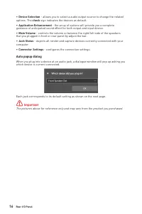
Page 28 - Auto popup dialog; which device is current connected.
16 Rear I/O Panel ∙ Device Selection - allows you to select a audio output source to change the related options. The check sign indicates the devices as default. ∙ Application Enhancement - the array of options will provide you a complete guidance of anticipated sound effect for both output and inpu...
Page 30 - Installing antennas; Screw the antennas tight to the antenna connectors as shown below.
18 Rear I/O Panel Installing antennas 1. Screw the antennas tight to the antenna connectors as shown below. 2. Orient the antennas. 1 2
Page 31 - Overview of Components
19 Overview of Components Overview of Components BAT1 SATA▼1▲2 JUSB3 JUSB4 ATX_PWR1 PUMP_FAN1 SYS_FAN6 JRAINBOW2 CPU_FAN1 DIMMB2 DIMMB1 DIMMA2 DIMMA1 SATA▼3▲4 SATA6 SATA5 Processor Socket CPU_PWR1 CPU_PWR2 JFP1 JFP2 SYS_FAN4 SYS_FAN5 JTPM1 JCI1 JBAT1 JUSB1 JUSB2 LED_SW1 PCIE_PWR1 SYS_FAN3 SYS_FAN2 J...
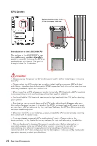
Page 32 - CPU Socket; Introduction to the LGA1200 CPU; notches
20 Overview of Components ⚠ Important ∙ Always unplug the power cord from the power outlet before installing or removing the CPU. ∙ Please retain the CPU protective cap after installing the processor. MSI will deal with Return Merchandise Authorization (RMA) requests if only the motherboard comes wi...
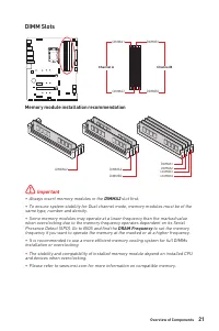
Page 33 - DIMM Slots; Memory module installation recommendation; Always insert memory modules in the; DRAM Frequency; to set the memory
21 Overview of Components DIMM Slots DIMMA1 DIMMB1 Channel A Channel B DIMMA2 DIMMB2 Memory module installation recommendation ⚠ Important ∙ Always insert memory modules in the DIMMA2 slot first. ∙ To ensure system stability for Dual channel mode, memory modules must be of the same type, number and ...
Page 34 - MSI; to support its weight to prevent deformation of the slot.; JAUD1: Front Audio Connector
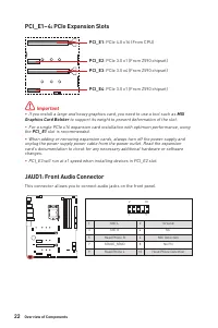
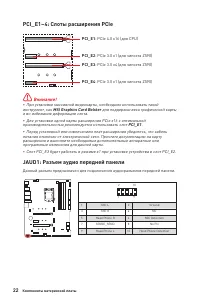
22 Overview of Components BAT1 PCI_E1~4: PCIe Expansion Slots PCI_E1 : PCIe 4.0 x16 (From CPU) PCI_E3 : PCIe 3.0 x4 (From Z590 chipset) PCI_E2 : PCIe 3.0 x1 (From Z590 chipset) PCI_E4 : PCIe 3.0 x1 (From Z590 chipset) ⚠ Important ∙ If you install a large and heavy graphics card, you need to use a to...
Page 35 - Installing M.2 module; Loosen the screws of M.2 SHIELD FROZR heatsink.; Intel® RST only supports PCIe M.2 SSD with UEFI ROM.; Video Demonstration; Watch the video to learn how to Install
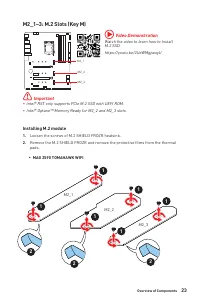
23 Overview of Components M2_1~3: M.2 Slots (Key M) Installing M.2 module 1. Loosen the screws of M.2 SHIELD FROZR heatsink. 2. Remove the M.2 SHIELD FROZR and remove the protective films from the thermal pads. M2_1 M2_2 M2_3 ⚠ Important ∙ Intel® RST only supports PCIe M.2 SSD with UEFI ROM. ∙ Intel...
Page 36 - Standoff
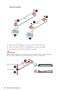
24 Overview of Components 3. Secure the supplied M.2 standoff according to your M.2 SSD length if need. 4. Insert your M.2 SSD into the M.2 slot at a 30-degree angle. 5. Secure the M.2 SSD in place with the supplied M.2 8.5H screw. ⚠ Important Skip step 3 and step 5, if you install 22110 M.2 into M2...
Page 37 - Put the M.2 SHIELD FROZR heatsink back in place and secure it.
25 Overview of Components 6. Put the M.2 SHIELD FROZR heatsink back in place and secure it. 6 6 6 6 6 6 6 6 ▪ MAG Z590 TORPEDO ▪ MAG Z590 TOMAHAWK WIFI 6 6
Page 38 - Slot
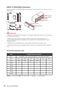
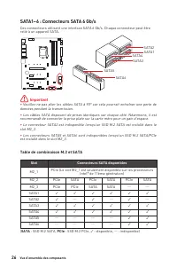
26 Overview of Components SATA1~6: SATA 6Gb/s Connectors These connectors are SATA 6Gb/s interface ports. Each connector can connect to one SATA device. SATA1 SATA3 SATA5 SATA2 SATA4 SATA6 ⚠ Important ∙ Please do not fold the SATA cable at a 90-degree angle. Data loss may result during transmission ...
Page 39 - JDASH1 : Tuning Controller connector
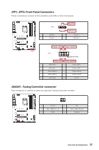
27 Overview of Components JFP1, JFP2: Front Panel Connectors These connectors connect to the switches and LEDs on the front panel. 1 2 10 9 + + + - - - - + Power LED HDD LED Reset Switch Reserved Power Switch JFP1 1 HDD LED + 2 Power LED + 3 HDD LED - 4 Power LED - 5 Reset Switch 6 Power Switch 7 Re...
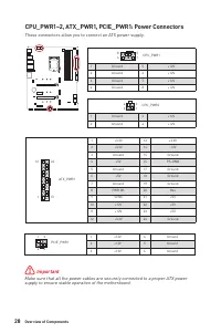
Page 40 - supply to ensure stable operation of the motherboard.
28 Overview of Components 24 13 1 12 ATX_PWR1 1 +3.3V 13 +3.3V 2 +3.3V 14 -12V 3 Ground 15 Ground 4 +5V 16 PS-ON# 5 Ground 17 Ground 6 +5V 18 Ground 7 Ground 19 Ground 8 PWR OK 20 Res 9 5VSB 21 +5V 10 +12V 22 +5V 11 +12V 23 +5V 12 +3.3V 24 Ground 5 4 1 8 CPU_PWR1 1 Ground 5 +12V 2 Ground 6 +12V 3 Gr...
Page 41 - sure to connect it with the corresponding orientation.
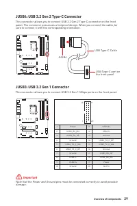
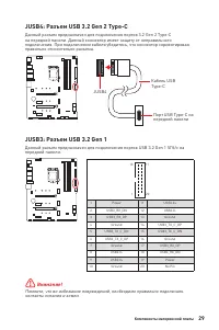
29 Overview of Components JUSB3: USB 3.2 Gen 1 Connector This connector allows you to connect USB 3.2 Gen 1 5Gbps ports on the front panel. ⚠ Important Note that the Power and Ground pins must be connected correctly to avoid possible damage. 1 10 11 20 1 Power 11 USB2.0+ 2 USB3_RX_DN 12 USB2.0- 3 US...
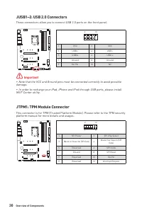
Page 42 - JTPM1: TPM Module Connector; platform manual for more details and usages.
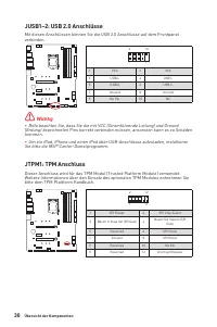
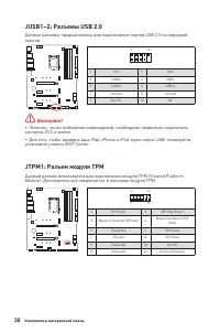
30 Overview of Components JUSB1~2: USB 2.0 Connectors These connectors allow you to connect USB 2.0 ports on the front panel. 1 2 10 9 1 VCC 2 VCC 3 USB0- 4 USB1- 5 USB0+ 6 USB1+ 7 Ground 8 Ground 9 No Pin 10 NC ⚠ Important ∙ Note that the VCC and Ground pins must be connected correctly to avoid pos...
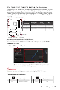
Page 43 - Switching fan mode and adjusting fan speed; HARDWARE MONITOR; Connector
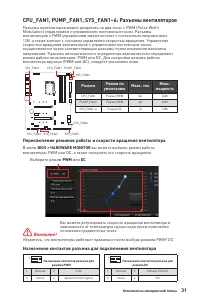
31 Overview of Components CPU_FAN1, PUMP_FAN1, SYS_FAN1~6: Fan Connectors Fan connectors can be classified as PWM (Pulse Width Modulation) Mode or DC Mode. PWM Mode fan connectors provide constant 12V output and adjust fan speed with speed control signal. DC Mode fan connectors control fan speed by ...
Page 44 - JCI1: Chassis Intrusion Connector; Using chassis intrusion detector
32 Overview of Components JCI1: Chassis Intrusion Connector This connector allows you to connect the chassis intrusion switch cable. Normal (default) Trigger the chassis intrusion event Using chassis intrusion detector 1. Connect the JCI1 connector to the chassis intrusion switch/ sensor on the chas...
Page 45 - Resetting BIOS to default values
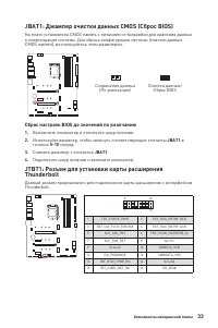
33 Overview of Components JBAT1: Clear CMOS (Reset BIOS) Jumper There is CMOS memory onboard that is external powered from a battery located on the motherboard to save system configuration data. If you want to clear the system configuration, set the jumpers to clear the CMOS memory. Keep Data (defau...
Page 46 - before installing or removing the RGB LED strip.; RGB LED Strip Connection
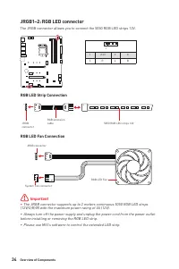
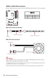
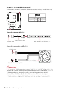
34 Overview of Components ⚠ Important ∙ The JRGB connector supports up to 2 meters continuous 5050 RGB LED strips (12V/G/R/B) with the maximum power rating of 3A (12V). ∙ Always turn off the power supply and unplug the power cord from the power outlet before installing or removing the RGB LED strip....
Page 47 - CAUTION; connector will result in damage to the LED strip.; JRAINBOW1~2: Addressable RGB LED connectors; Addressable RGB LED strips 5V.; Addressable RGB LED Strip Connection
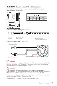
35 Overview of Components 1 1 1 D +5V ⚠ CAUTION Do not connect the wrong type of LED strips. The JRGB connector and the JRAINBOW connector provide different voltages, and connecting the 5V LED strip to the JRGB connector will result in damage to the LED strip. ⚠ Important ∙ The JRAINBOW connector su...
Page 48 - EZ Debug LED; These LEDs indicate the debug status of the motherboard.; - indicates CPU is not detected or fail.; DRAM; - indicates DRAM is not detected or fail.; VGA; - indicates GPU is not detected or fail.; BOOT; - indicates the booting device is not detected; Onboard LEDs; This switch is used to switch on/ off all the LEDs of motherboard.
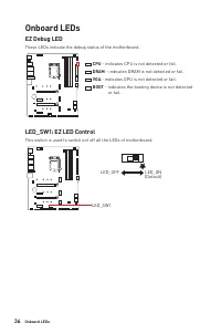
36 Onboard LEDs EZ Debug LED These LEDs indicate the debug status of the motherboard. CPU - indicates CPU is not detected or fail. DRAM - indicates DRAM is not detected or fail. VGA - indicates GPU is not detected or fail. BOOT - indicates the booting device is not detected or fail. Onboard LEDs LED...
Page 49 - Installing Windows® 10; Restart; key during the computer POST (Power-On Self Test) to get into Boot; Installing Drivers; Select to choose what happens with this disc; button in the lower-right corner of the window.; OK; MSI Center; MSI Center User Guide
37 Installing OS, Drivers & MSI Center Installing OS, Drivers & MSI Center Please download and update the latest utilities and drivers at www.msi.com Installing Windows® 10 1. Power on the computer. 2. Insert the Windows® 10 installation disc/USB into your computer. 3. Press the Restart butt...
Page 50 - UEFI BIOS; - this motherboard supports only 64-bit Windows
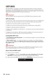
38 UEFI BIOS UEFI BIOS MSI UEFI BIOS is compatible with UEFI (Unified Extensible Firmware Interface) architecture. The UEFI BIOS firmware infrastructure has many new functions and advantages that traditional BIOS cannot achieve. It will fully support future PCs and devices that comply with UEFI firm...
Page 51 - BIOS Setup; always keep the default settings; HELP; Entering BIOS Setup; Delete; Function key; BIOS User Guide
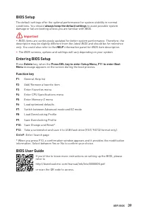
39 UEFI BIOS BIOS Setup The default settings offer the optimal performance for system stability in normal conditions. You should always keep the default settings to avoid possible system damage or failure booting unless you are familiar with BIOS. ⚠ Important ∙ BIOS items are continuously updated fo...
Page 52 - Resetting BIOS; Updating BIOS; Updating BIOS with M-FLASH
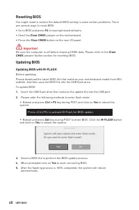
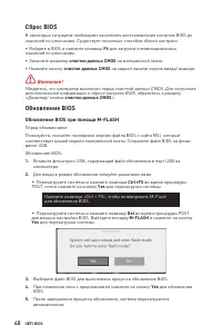
40 UEFI BIOS Resetting BIOS You might need to restore the default BIOS setting to solve certain problems. There are several ways to reset BIOS: ∙ Go to BIOS and press F6 to load optimized defaults. ∙ Short the Clear CMOS jumper on the motherboard. ∙ Press the Clear CMOS button on the rear I/O panel....
Page 53 - Updating the BIOS with MSI Center
41 UEFI BIOS Updating the BIOS with MSI Center Before updating: ∙ Make sure the LAN driver is already installed and the internet connection is set properly. ∙ Please close all other application software before updating the BIOS. To update BIOS: 1. Install and launch MSI CENTER and go to Support page...
Page 55 - Inhalt; Hinweise zum Geh
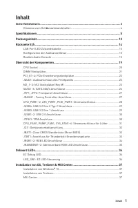
1 Inhalt Inhalt Sicherheitshinweis ..................................................................................................... 3 Hinweise zum Geh ä useabstandshalter ................................................................. 4 Spezifikationen ...........................................
Page 56 - BIOS-Benutzerhandbuch
2 Inhalt UEFI BIOS ............................................................................................................. 38 BIOS Setup ............................................................................................................ 39Öffnen des BIOS Setups...........................
Page 57 - Sicherheitshinweis
3 Inhalt Sicherheitshinweis ∙ Die im Paket enthaltene Komponenten sind der Beschädigung durch elektrostatischen Entladung (ESD). Beachten Sie bitte die folgenden Hinweise, um die erfolgreichen Computermontage sicherzustellen. ∙ Stellen Sie sicher, dass alle Komponenten fest angeschlossen sind. Locke...
Page 58 - Hinweise zum Gehäuseabstandshalter
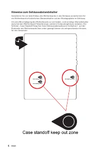
4 Inhalt Hinweise zum Gehäuseabstandshalter Installieren Sie vor dem Einbau des Motherboards in das Gehäuse zunächst den für ein Motherboard erforderlichen Abstandshalter auf der Montageplatte im Gehäuse. Um eine Beschädigung des Motherboards zu vermeiden, sind unnötige Abstandshalter zwischen den M...
Page 59 - Spezifikationen; Unterstützt non-ECC, ungepufferte Speicher; anschlüsse; Unterstützt die 2-Wege AMD® CrossFire
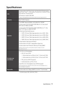
5 Spezifikationen Spezifikationen CPU ∙ Unterstützt Intel® Core ™ der 10. Generation Prozessoren, Intel® Core ™ der 11. Generation Prozessoren, Pentium® Gold und Celeron® Prozessoren* ∙ Prozessor Sockel LGA1200 * Weitere Kompatibilitätsinformationen finden Sie unter www.intel.com. Chipsatz Intel® Z5...
Page 60 - Aufbewahrung; RAID
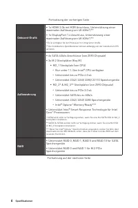
6 Spezifikationen Fortsetzung der vorherigen Seite Onboard-Grafik ∙ 1x HDMI 2.0b mit HDR Anschluss, Unterstützung einer maximalen Auflösung von 4K 60Hz*/** ∙ 1x DisplayPort 1.4 Anschluss, Unterstützung einer maximalen Auflösung von 4K 60Hz*/** * Es ist verfügbar für den Prozessor mit integrierter Gr...
Page 61 - USB; interner Anschluss, 1 Typ-A Anschluss an der
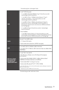
7 Spezifikationen Fortsetzung der vorherigen Seite USB ∙ Intel® Z590 Chipsatz ▪ 1x USB3.2 Gen2x2 20Gbit/s Typ-C Anschluss an der rückseitigen Anschlussleiste ▪ 2x USB 3.2 Gen 2 10Gbit/s Anschlüsse (1 Typ-C interner Anschluss, 1 Typ-A Anschluss an der rückseitigen Anschlussleiste) ▪ 6x USB 3.2 Gen 1 ...
Page 62 - Interne Anschlüsse
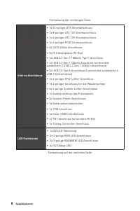
8 Spezifikationen Fortsetzung der vorherigen Seite Interne Anschlüsse ∙ 1x 24-poliger ATX Stromanschluss ∙ 1x 8-poliger ATX 12V Stromanschluss ∙ 1x 4-poliger ATX 12V Stromanschluss ∙ 1x 6-poliger PCIE Stromanschluss ∙ 6x SATA 6Gb/s Anschlüsse ∙ 3x M.2 Steckplätze (M-Key) ∙ 1x USB 3.2 Gen 2 10Gbit/s ...
Page 63 - Ausgänge; x Wi-Fi Antennenanschlüsse (Nur für MAG Z590
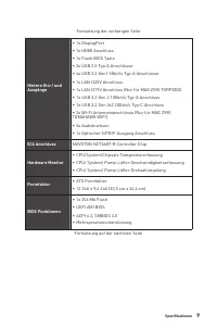
9 Spezifikationen Fortsetzung der vorherigen Seite Hintere Ein-/ und Ausgänge ∙ 1x DisplayPort ∙ 1x HDMI Anschluss ∙ 1x Flash BIOS Taste ∙ 2x USB 2.0 Typ-A Anschlüsse ∙ 4x USB 3.2 Gen1 5Gbit/s Typ-A Anschlüsse ∙ 1x LAN I225V Anschluss ∙ 1x LAN I219V Anschluss (Nur für MAG Z590 TORPEDO) ∙ 1x USB 3.2 ...
Page 65 - Besondere; Smart-Lüftersteuerung
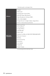
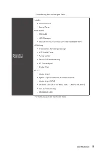
11 Spezifikationen Fortsetzung der vorherigen Seite Besondere Funktionen ∙ Audio ▪ Audio Boost 5 ▪ Sound Tune ∙ Netzwerk ▪ 2.5G LAN ▪ LAN Manager ▪ Intel Wi-Fi (Nur für MAG Z590 TOMAHAWK WIFI) ∙ Kühlung ▪ Erweitertes Kühlkörperdesign ▪ M.2 Shield Frozr ▪ Pump - Lüfter ▪ Smart-Lüftersteuerung ▪ K7 Th...
Page 66 - Multi GPU-CrossFire Technologie
12 Spezifikationen Fortsetzung der vorherigen Seite Besondere Funktionen ∙ Leistung ▪ Multi GPU-CrossFire Technologie ▪ DDR4 Boost ▪ Core Boost ▪ GAME Boost ▪ Lightning USB 20G ▪ USB 3.2 Gen 2 10G ▪ USB Anschluss mit Typ A+C ▪ Front USB Typ-C ▪ Dual CPU Power ▪ Lightning Gen 4 PCI-E Slot ▪ Lightning...
Page 67 - Packungsinhalt; USB-Laufwerk mit Treibern und; Kabel; Wi-Fi Antenne (Nur für MAG Z590 TOMAHAWK; Wichtig
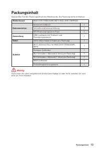
13 Packungsinhalt Packungsinhalt Überprüfen Sie den Packungsinhalt des Mainboards. Die Packung sollte enthalten: Motherboard MAG Z590 TOMAHAWK WIFI/ MAG Z590 TORPEDO Dokumentation Benutzerhandbuch 1 Schnellinstallationsanleitung 1 MSI Prämienprogramm Flyer 1 Anwendung USB-Laufwerk mit Treibern und D...
Page 68 - BIOS-Aktualisierung per Flash BIOS Taste.
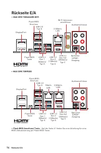
14 Rückseite E/A Rückseite E/A ∙ MAG Z590 TOMAHAWK WIFI ∙ Flash BIOS Anschluss/ Taste - Auf der Seite 41 finden Sie eine Anleitung für eine BIOS-Aktualisierung per Flash BIOS Taste. USB 3.2 Gen 2x2 (20Gbit/s) Typ-C USB 3.2 Gen 2x2 (20Gbit/s) Typ-C Flash BIOS Taste Flash BIOS Taste 2.5Gbit/s LAN 2,5G...
Page 69 - Konfiguration der Audioanschlüsse; Audioanschlüsse; LAN Port LED Zustandstabelle; Bezeichnung
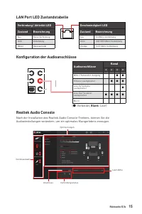
15 Rückseite E/A Konfiguration der Audioanschlüsse Audioanschlüsse Kanal 2 4 6 8 Mitte-/ Subwoofer-Ausgang ● ● Hinterer Lautsprecher ● ● ● Line-In/ Seitliche Lautsprecher ● Line-Out/ Vorderer Lautsprecher ● ● ● ● Mic In (●: Verbindet, Blank : Leer) LAN Port LED Zustandstabelle Verbindung/ Aktivität ...
Page 70 - Geräteauswahl; - Ermöglicht die Auswahl der Audio-Ausgangs Quelle. Das aktuell; Optimierungen; - Die Vielfalt an Optionen bietet eine komplette Anleitung von; Lautstärke; die im Front-Panel oder auf der Rückseite des PCs eingesteckt sind.; Verbindungsstatus; - Konfiguriert die Anschlusseinstellungen.; erworbenen Produkt abweichen.
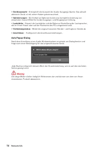
16 Rückseite E/A ∙ Geräteauswahl - Ermöglicht die Auswahl der Audio-Ausgangs Quelle. Das aktuell aktivierte Gerät ist mit einem Haken gekennzeichnet. ∙ Optimierungen - Die Vielfalt an Optionen bietet eine komplette Anleitung von erwarteten Sound-Effekt für beide Ausgangs- und Eingangsvorrichtung. ∙ ...
Page 72 - Antennen installieren; Richten Sie die Antennenspitzen aus.
18 Rückseite E/A Antennen installieren 1. Schrauben Sie die Antennen fest an die Antennenanschlüsse, wie gezeigt. 2. Richten Sie die Antennenspitzen aus. 1 2
Page 73 - Übersicht der Komponenten
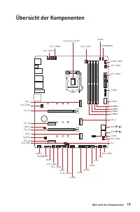
19 Übersicht der Komponenten Übersicht der Komponenten BAT1 SATA▼1▲2 JUSB3 JUSB4 ATX_PWR1 PUMP_FAN1 SYS_FAN6 JRAINBOW2 CPU_FAN1 DIMMB2 DIMMB1 DIMMA2 DIMMA1 SATA▼3▲4 SATA6 SATA5 Prozessor Sockel CPU_PWR1 CPU_PWR2 JFP1 JFP2 SYS_FAN4 SYS_FAN5 JTPM1 JCI1 JBAT1 JUSB1 JUSB2 LED_SW1 PCIE_PWR1 SYS_FAN3 SYS_...
Page 74 - Ziehen Sie das Netzkabel ab, bevor Sie die CPU ein- und ausbauen.; CPU Sockel; Justierungen
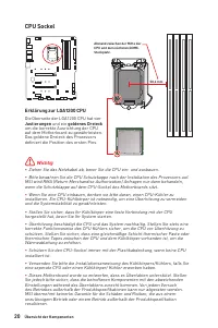
20 Übersicht der Komponenten ⚠ Wichtig ∙ Ziehen Sie das Netzkabel ab, bevor Sie die CPU ein- und ausbauen. ∙ Bitte bewahren Sie die CPU Schutzkappe nach der Installation des Prozessors auf. MSI wird RMA (Return Merchandise Authorization) Anfragen nur dann behandeln, wenn die Schutzklappe auf dem CPU...
Page 75 - DIMM Steckplätze; Stellen Sie im BIOS-Setup mit; die Speicherfrequenz ein, wenn Sie
21 Übersicht der Komponenten DIMM Steckplätze DIMMA1 DIMMB1 Kanal A Kanal B DIMMA2 DIMMB2 Memory module installation recommendation ⚠ Wichtig ∙ Um einen sicheren Systemstart zu gewährleisten, bestücken Sie immer DIMMA2 zuerst. ∙ Stellen Sie im Dual-Kanal-Modus bitte sicher, dass Sie Module des gleic...
Page 76 - der das Gewicht trägt und eine; JAUD1: Audioanschluss des Frontpanels
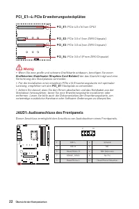
22 Übersicht der Komponenten BAT1 PCI_E1~4: PCIe Erweiterungssteckplätze PCI_E1 : PCIe 4.0 x16 (von CPU) PCI_E3 : PCIe 3.0 x4 (von Z590 Chipsatz) PCI_E2 : PCIe 3.0 x1 (von Z590 Chipsatz) PCI_E4 : PCIe 3.0 x1 (From Z590 Chipsatz) ⚠ Wichtig ∙ Wenn Sie eine große und schwere Grafikkarte einbauen, benöt...
Page 77 - Installation eines M.2 Moduls; Intel® RST unterstützt nur PCIe M.2 SSD mit UEFI ROM.
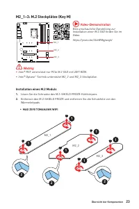
23 Übersicht der Komponenten M2_1~3: M.2 Steckplätze (Key M) Installation eines M.2 Moduls 1. Lösen Sie die Schraube des M.2-SHIELD FROZR-Kühlkörpers. 2. Entfernen den M.2-SHIELD FROZR und entfernen Sie die Schutzfolie von den Wärmeleitpads. M2_1 M2_2 M2_3 ⚠ Wichtig ∙ Intel® RST unterstützt nur PCIe...
Page 78 - Wählen Sie die Montageposition entsprechend Ihrer M.2 SSD Länge.; Abstandshalter
24 Übersicht der Komponenten 3. Wählen Sie die Montageposition entsprechend Ihrer M.2 SSD Länge. 4. Stecken Sie eine M.2-SSD im 30-Grad-Winkel in den M.2-Steckplatz . 5. Schrauben Sie den M.2 SSD mit 8,5H M.2-Schraube. ⚠ Wichtig Überspringen Sie Schritt 3 und Schritt 5, wenn Sie eine 22110 M.2 in de...
Page 80 - Steckplatz
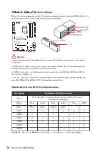
26 Übersicht der Komponenten SATA1~6: SATA 6Gb/s Anschlüsse Dieser Anschluss basiert auf der Hochgeschwindigkeitsschnittstelle SATA 6 Gb/s. Pro Anschluss kann ein SATA Gerät angeschlossen werden. SATA1 SATA3 SATA5 SATA2 SATA4 SATA6 ⚠ Wichtig ∙ Knicken Sie das SATA-Kabel nicht in einem 90° Winkel. Da...
Page 82 - Mit diesen Anschlüssen verbinden Sie die ATX Stromstecker.
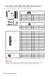
28 Übersicht der Komponenten 24 13 1 12 ATX_PWR1 1 +3.3V 13 +3.3V 2 +3.3V 14 -12V 3 Ground 15 Ground 4 +5V 16 PS-ON# 5 Ground 17 Ground 6 +5V 18 Ground 7 Ground 19 Ground 8 PWR OK 20 Res 9 5VSB 21 +5V 10 +12V 22 +5V 11 +12V 23 +5V 12 +3.3V 24 Ground 5 4 1 8 CPU_PWR1 1 Ground 5 +12V 2 Ground 6 +12V 3...
Page 83 - Anschluss auf dem
29 Übersicht der Komponenten JUSB3: USB 3.2 Gen 1 Anschluss Mit diesem Anschluss können Sie die USB 3.2 Gen 1 Anschlüsse auf dem Frontpanel verbinden. ⚠ Wichtig Bitte beachten Sie, dass Sie die mit „Stromführende Leitung“ und „Erdleitung“ bezeichneten Pins korrekt verbinden müssen, ansonsten kann es...
Page 84 - Sie bitte die MSI® Center-Dienstprogramm.
30 Übersicht der Komponenten JUSB1~2: USB 2.0 Anschlüsse Mit diesen Anschlüssen können Sie die USB 2.0 Anschlüsse auf dem Frontpanel verbinden. 1 2 10 9 1 VCC 2 VCC 3 USB0- 4 USB1- 5 USB0+ 6 USB1+ 7 Ground 8 Ground 9 No Pin 10 NC ⚠ Wichtig ∙ Bitte beachten Sie, dass Sie die mit VCC (Stromführende Le...
Page 85 - Lüfter; oder Spannungsmodus betrieben werden. Im PWM-Modus bieten die; Umschalten des Lüfter-Modus und Anpassung der Lüfterdrehzahl; BIOS > HARDWARE MONITOR; Anpasssung der Lüfterdrehzahl in Abhängigkeit von der CPU-; Pin-Belegung der Lüfteranschlüsse; Anschluss
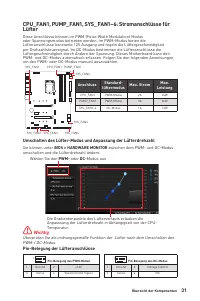
31 Übersicht der Komponenten CPU_FAN1, PUMP_FAN1, SYS_FAN1~6: Stromanschlüsse für Lüfter Diese Anschlüsse können im PWM (Pulse Width Modulation) Modus oder Spannungsmodus betrieben werden. Im PWM-Modus bieten die Lüfteranschlüsse konstante 12V Ausgang und regeln die Lüftergeschwindigkeit per Drehzah...
Page 86 - JCI1: Gehäusekontaktanschluss; Gehäusekontakt-Detektor verwenden
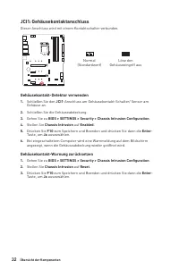
32 Übersicht der Komponenten JCI1: Gehäusekontaktanschluss Dieser Anschluss wird mit einem Kontaktschalter verbunden. Normal (Standardwert) Löse den Gehäuseeingriff aus Gehäusekontakt-Detektor verwenden 1. Schließen Sie den JCI1 -Anschluss am Gehäusekontakt-Schalter/ Sensor am Gehäuse an. 2. Schließ...
Page 87 - Rücksetzen des BIOS auf Standardwerte; JTBT1: Anschluss für Thunderbolt-Erweiterungskarte; Mit diesem Anschluss können Sie eine Ein-/Ausgang der Thunderbolt-
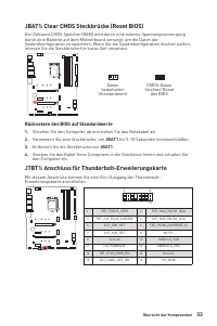
33 Übersicht der Komponenten JBAT1: Clear CMOS Steckbrücke (Reset BIOS) Der Onboard CMOS Speicher (RAM) wird durch eine externe Spannungsversorgung durch eine Batterie auf dem Motherboard versorgt, um die Daten der Systemkonfiguration zu speichern. Wenn Sie die Systemkonfiguration löschen wollen, mü...
Page 89 - JRAINBOW1~2: Adressierbare RGB LED Anschlüsse; ACHTUNG
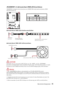
35 Übersicht der Komponenten JRAINBOW1~2: Adressierbare RGB LED Anschlüsse JRAINBOW ermöglicht den Anschluss von WS2812B einzeln adressierbaren RGB- LED-Streifen (5 V). 1 1 +5V 2 Data 3 No Pin 4 Ground 1 D +5V ⚠ ACHTUNG Schließen Sie nur passende LED-Streifen an. Der JRGB- und der JRAINBOW- Anschlus...
Page 90 - Diese LEDs zeigen d; - CPU wird nicht erkannt oder ist fehlerhaft.; - DRAM wird nicht erkannt oder ist; - GPU wird nicht erkannt oder ist fehlerhaft.; - Boot-Gerät wird nicht erkannt oder ist
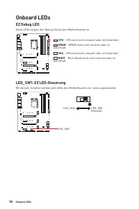
36 Onboard LEDs EZ Debug LED Diese LEDs zeigen d en Debug-Status des Mo therboards an. CPU - CPU wird nicht erkannt oder ist fehlerhaft. DRAM - DRAM wird nicht erkannt oder ist fehlerhaft. VGA - GPU wird nicht erkannt oder ist fehlerhaft. BOOT - Boot-Gerät wird nicht erkannt oder ist fehlerhaft. Onb...
Page 91 - Installation von OS, Treibern & MSI Center; Installation von Windows® 10; 0 Disk oder das USB-Flashlaufwerk in das optisches; Installation von Treibern; Hauptverzeichnis des MSI USB-Laufwerk auch manuell ausführen.; MSI Center Benutzerhandbuch
37 Installation von OS, Treibern & MSI Center Installation von OS, Treibern & MSI Center Laden Sie die neuesten Treiber und Dienstprogramme von www.msi.com herunter und aktualisieren Sie sie. Installation von Windows® 10 1. Schalten Sie den Computer ein. 2. Legen Sie die Windows® 10 Disk ode...
Page 92 - Ältere Grafikkarten -; Während des BOOT-Vorgangs drücken Sie die Taste; ENTF
38 UEFI BIOS UEFI BIOS Das MSI UEFI-BIOS ist mit der UEFI-Architektur (Unified Extensible Firmware Interface) kompatibel. Das UEFI-BIOS hat viele neue Funktionen und besitzt Vorteile, die das traditionelle BIOS nicht bieten kann. Es wird zukünftige PCs und Geräte, die der UEFI-Firmware-Architektur e...
Page 93 - Öffnen des BIOS Setups; Funktionstasten
39 UEFI BIOS BIOS Setup Die Standardeinstellungen bieten die optimale Leistung für die Systemstabilität unter Normalbedingungen. Sie sollten immer die Standardeinstellungen behalten , um mögliche Schäden des Systems oder Boot-Fehler zu vermeiden, außer Sie besitzen ausreichende BIOS Kenntnisse. ⚠ Wi...
Page 94 - Reset des BIOS; Clear CMOS Steckbrücke; Bitte lesen Sie für Informationen zum BIOS-Reset im Bereich; „Clear CMOS; Aktualisierung des BIOS; Aktualisierung des BIOS mit dem M-FLASH-Programm; Beim Neustart drücken Sie während des POST-Vorgangs die Taste
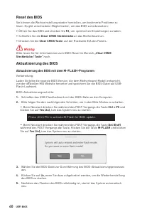
40 UEFI BIOS Reset des BIOS Sie können die Werkseinstellung wieder herstellen, um bestimmte Probleme zu lösen. Es gibt verschiedene Möglichkeiten, um das BIOS zurückzusetzen: ∙ Öffnen Sie das BIOS und drücken Sie F6 , um optimierten Einstellungen zu laden. ∙ Schließen Sie die Clear CMOS Steckbrücke ...
Page 95 - Aktualisierung des BIOS mit MSI Center; Support; Wählen Sie die BIOS-Datei aus und klicken Sie auf das; Install; Aktualisierung des BIOS mit Flash BIOS Taste
41 UEFI BIOS Aktualisierung des BIOS mit MSI Center Vorbereitung: ∙ Stellen Sie sicher, dass zuvor die LAN-Treiber installiert wurden und eine Internetverbindung eingerichtet ist. ∙ Bitte schließen Sie jegliche andere Anwendungssoftware, bevor Sie das BIOS aktualisieren.Schritte zur Aktualisierung d...
Page 97 - Table des matières
1 Table des matières Table des matières Informations de sécurité ....................................................................................... 3 Avertissement pour l’installation des entretoises ................................................ 4 Spécifications ................................
Page 99 - Informations de sécurité; veuillez vous référer aux instructions ci-dessous.
3 Informations de sécurité Informations de sécurité ∙ Les composants dans l’emballage peuvent être endommagés par des décharges électrostatiques (ESD). Pour vous assurer de correctement monter votre ordinateur, veuillez vous référer aux instructions ci-dessous. ∙ Assurez-vous de bien connecter tous ...
Page 100 - Avertissement pour l’installation des entretoises; indiqué ci-dessous) pour servir d’avertissement à l’utilisateur.
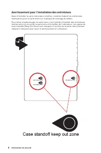
4 Informations de sécurité Avertissement pour l’installation des entretoises Avant d’installer la carte mère dans le boîtier, installez d’abord les entretoises nécessaires pour la carte mère sur la plaque de montage du boîtier. Pour éviter d’endommager la carte mère, il est interdit d’installer des ...
Page 101 - Spécifications; AMD® CrossFireTM 2-Way
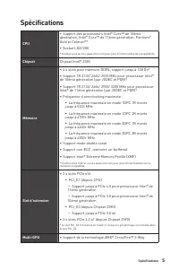
5 Spécifications Spécifications CPU ∙ Support des processeurs Intel® Core™ de 10ème génération, Intel® Core™ de 11ème génération, Pentium® Gold et Celeron®* ∙ Socket LGA1200 * Veuillez vous au site www.intel.com pour plus d’informations de compatibilité. Chipset Chipset Intel® Z590 Mémoire ∙ 4 x slo...
Page 102 - Sorties vidéo
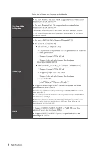
6 Spécifications Suite du tableau sur la page précédente Sorties vidéo intégrées ∙ 1 x port HDMI 2.0b avec HDR, supportant une résolution maximum de 4K 60 Hz*/** ∙ 1 x port DisplayPort 1.4, supportant une résolution maximum de 4K 60 Hz*/** * Disponible uniquement pour le processeur avec puce graphiq...
Page 104 - Connecteurs
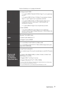
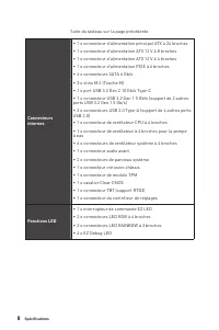
8 Spécifications Suite du tableau sur la page précédente Connecteurs internes ∙ 1 x connecteur d’alimentation principal ATX à 24 broches ∙ 1 x connecteur d’alimentation ATX 12 V à 8 broches ∙ 1 x connecteur d’alimentation ATX 12 V à 4 broches ∙ 1 x connecteur d’alimentation PCIE à 6 broches ∙ 6 x co...
Page 105 - Connecteurs sur le; x connecteurs d’antenne Wi-Fi (Uniquement pour MAG; Moniteur système
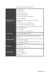
9 Spécifications Suite du tableau sur la page précédente Connecteurs sur le panneau arrière ∙ 1 x DisplayPort ∙ 1 x port HDMI ∙ 1 x bouton Flash BIOS ∙ 2 x ports USB 2.0 Type-A ∙ 4 x ports USB 3.2 Gen1 5 Gb/s Type-A ∙ 1 x port LAN I225V ∙ 1 x port LAN I219V (Uniquement pour MAG Z590 TORPEDO) ∙ 1 x p...
Page 106 - Logiciel
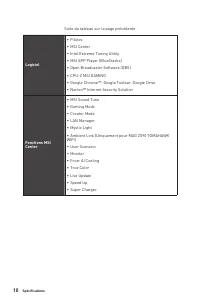
10 Spécifications Suite du tableau sur la page précédente Logiciel ∙ Pilotes ∙ MSI Center ∙ Intel Extreme Tuning Utility ∙ MSI APP Player (BlueStacks) ∙ Open Broadcaster Software (OBS) ∙ CPU-Z MSI GAMING ∙ Google Chrome™, Google Toolbar, Google Drive ∙ Norton™ Internet Security Solution Fonctions MS...
Page 107 - Fonctions spéciales; Intel Wi-Fi (Uniquement pour MAG Z590 TOMAHAWK
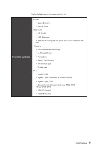
11 Spécifications Suite du tableau sur la page précédente Fonctions spéciales ∙ Audio ▪ Audio Boost 5 ▪ Sound Tune ∙ Network ▪ 2,5 G LAN ▪ LAN Manager ▪ Intel Wi-Fi (Uniquement pour MAG Z590 TOMAHAWK WIFI) ∙ Cooling ▪ Extended Heatsink Design ▪ M.2 Shield Frozr ▪ Pump Fan ▪ Smart Fan Control ▪ K7 th...
Page 108 - Lightning Gen 4 PCI-E Slot
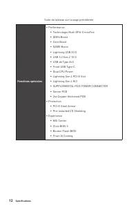
12 Spécifications Suite du tableau sur la page précédente Fonctions spéciales ∙ Performance ▪ Technologie Multi GPU-CrossFire ▪ DDR4 Boost ▪ Core Boost ▪ GAME Boost ▪ Lightning USB 20 G ▪ USB 3.2 Gen 2 10 G ▪ USB de Type A+C ▪ Front USB Type-C ▪ Dual CPU Power ▪ Lightning Gen 4 PCI-E Slot ▪ Lightnin...
Page 109 - Contenu; Carte mère
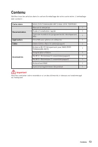
13 Contenu Contenu Vérifiez tous les articles dans le carton d’emballage de votre carte mère. L’emballage doit contenir : Carte mère MAG Z590 TOMAHAWK WIFI/ MAG Z590 TORPEDO Documentation Manuel d’utilisation 1 Guide d’installation rapide 1 Carte de membre du programme de récompenses MSI 1 Applicati...
Page 110 - Panneau arrière Entrée / Sortie; - Veuillez vous référer à la page 42 pour la mise à jour du
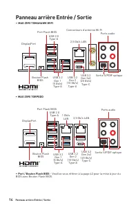
14 Panneau arrière Entrée / Sortie Panneau arrière Entrée / Sortie ∙ MAG Z590 TOMAHAWK WIFI ∙ Port / Bouton Flash BIOS - Veuillez vous référer à la page 42 pour la mise à jour du BIOS avec Bouton Flash BIOS. USB 3.2 Gen 2x2 (20 Gb/s) Type-C USB 3.2 Gen 2x2 (20 Gb/s) Type-C Bouton Flash BIOS Bouton F...
Page 111 - Configuration des ports audio; LED indiquant la connexion; paramètres du son afin d’obtenir une meilleure expérience sonore.; Ports audio; Espace
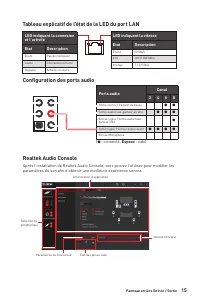
15 Panneau arrière Entrée / Sortie Configuration des ports audio Tableau explicatif de l’état de la LED du port LAN LED indiquant la connexion et l’activitéEtat Description Eteint Pas de connexion Jaune Connexion correcte Clignote Activité en cours LED indiquant la vitesseEtat Description Eteint 10 ...
Page 112 - Sélection du périphérique; - vous permet de sélectionner une source de sortie; Amélioration d’application; - les diverses options vous fournissent un guide complet; Volume principal; - contrôle le volume ou équilibre le son gauche/droite des haut-; Etat des prises Jack; - présente tous les périphériques de diffusion et de capture; Paramètres du connecteur; - configure les paramètres de connexion.; le produit que vous avez acheté.
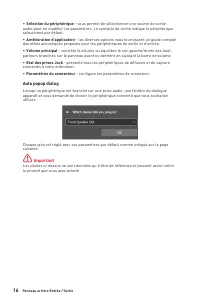
16 Panneau arrière Entrée / Sortie ∙ Sélection du périphérique - vous permet de sélectionner une source de sortie audio pour en modifier les paramètres. Le symbole de coche indique le périphérique sélectionné par défaut. ∙ Amélioration d’application - les diverses options vous fournissent un guide c...
Page 114 - Installation des antennes; Orientez les antennes.
18 Panneau arrière Entrée / Sortie Installation des antennes 1. Vissez fermement les antennes aux connecteurs dédiés, comme illustré ici. 2. Orientez les antennes. 1 2
Page 115 - Vue d’ensemble des composants
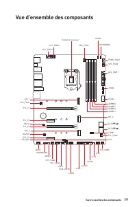
19 Vue d’ensemble des composants Vue d’ensemble des composants BAT1 SATA▼1▲2 JUSB3 JUSB4 ATX_PWR1 PUMP_FAN1 SYS_FAN6 JRAINBOW2 CPU_FAN1 DIMMB2 DIMMB1 DIMMA2 DIMMA1 SATA▼3▲4 SATA6 SATA5 Scoket processeur CPU_PWR1 CPU_PWR2 JFP1 JFP2 SYS_FAN4 SYS_FAN5 JTPM1 JCI1 JBAT1 JUSB1 JUSB2 LED_SW1 PCIE_PWR1 SYS_...
Page 116 - Socket Processeur; Présentation du socket LGA1200; encoches
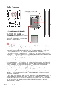
20 Vue d’ensemble des composants ⚠ Important ∙ Avant d’installer ou de retirer le processeur du socket, veillez à toujours débrancher le câble d’alimentation de la prise électrique. ∙ Veuillez garder le capot de protection du processeur après l’installation du processeur. Selon les exigences de RMA ...
Page 117 - Slots DIMM; Installation recommandée de module mémoire; en; pour régler la fréquence de mémoire si vous voulez faire
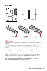
21 Vue d’ensemble des composants Slots DIMM DIMMA1 DIMMB1 Canal A Canal B DIMMA2 DIMMB2 Installation recommandée de module mémoire ⚠ Important ∙ Veillez à toujours insérer un module de mémoire dans l’emplacement DIMMA2 en premier. ∙ Pour garantir la stabilité du système au mode de double canal, assu...
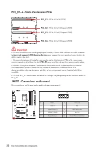
Page 118 - la; barre de support MSI Gaming Series; pour supporter son poids et pour éviter la; JAUD1 : Connecteur audio avant; Ce connecteur se lie aux jacks audio du panneau avant.
22 Vue d’ensemble des composants BAT1 PCI_E1~4 : Slots d’extension PCIe PCI_E1 : PCIe 4.0 x16 (CPU) PCI_E3 : PCIe 3.0 x4 (Chipset Z590) PCI_E2 : PCIe 3.0 x1 (Chipset Z590) PCI_E4 : PCIe 3.0 x1 (Chipset Z590) ⚠ Important ∙ Si vous installez une carte graphique lourde, il vous faut utiliser un outil c...
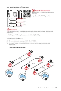
Page 119 - Installation du module M.2; Desserrez la vis de la plaque M.2 SHIELD FROZR.; Référez-vous à la vidéo d’installation du
23 Vue d’ensemble des composants M2_1~3 : Slots M.2 (Touche M) Installation du module M.2 1. Desserrez la vis de la plaque M.2 SHIELD FROZR. 2. Retirez la plaque M.2 SHIELD FROZR et retirez le film de protection du pad thermique. M2_1 M2_2 M2_3 ⚠ Important ∙ La technologie Intel® RST supporte seulem...
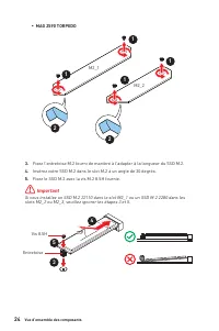
Page 120 - Insérez votre SSD M.2 dans le slot M.2 à un angle de 30 degrés.; Entretoise
24 Vue d’ensemble des composants 3. Fixez l’entretoise M.2 fourni de manière à l’adapter à la longueur du SSD M.2. 4. Insérez votre SSD M.2 dans le slot M.2 à un angle de 30 degrés. 5. Fixez le SSD M.2 avec la vis M.2 8.5H fournie. ⚠ Important Si vous installez un SSD M.2 22110 dans le slot M2_1 ou ...
Page 123 - JFP1, JFP2 : Connecteurs de panneau avant
27 Vue d’ensemble des composants JFP1, JFP2 : Connecteurs de panneau avant Ces connecteurs se lient aux interrupteurs et indicateurs LED du panneau avant. 1 2 10 9 + + + - - - - + Power LED HDD LED Reset Switch Reserved Power Switch JFP1 1 HDD LED + 2 Power LED + 3 HDD LED - 4 Power LED - 5 Reset Sw...
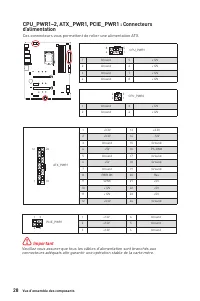
Page 124 - d’alimentation; Ces connecteurs vous permettent de relier une alimentation ATX.
28 Vue d’ensemble des composants 24 13 1 12 ATX_PWR1 1 +3.3V 13 +3.3V 2 +3.3V 14 -12V 3 Ground 15 Ground 4 +5V 16 PS-ON# 5 Ground 17 Ground 6 +5V 18 Ground 7 Ground 19 Ground 8 PWR OK 20 Res 9 5VSB 21 +5V 10 +12V 22 +5V 11 +12V 23 +5V 12 +3.3V 24 Ground 5 4 1 8 CPU_PWR1 1 Ground 5 +12V 2 Ground 6 +1...
Page 125 - afin d’éviter d’endommager la carte.
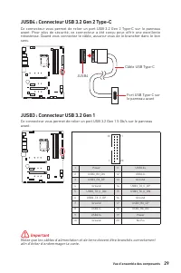
29 Vue d’ensemble des composants JUSB3 : Connecteur USB 3.2 Gen 1 Ce connecteur vous permet de relier un port USB 3.2 Gen 1 5 Gb/s sur le panneau avant. ⚠ Important Notez que les câbles d’alimentation et de terre doivent être branchés correctement afin d’éviter d’endommager la carte. 1 10 11 20 1 Po...
Page 126 - installer l’utilitaire MSI® .; JTPM1 : Connecteur de module TPM; référer au manuel du module TPM pour plus d’informations.
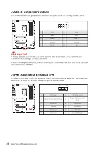
30 Vue d’ensemble des composants JUSB1~2 : Connecteurs USB 2.0 Ces connecteurs vous permettent de relier des ports USB 2.0 sur le panneau avant. 1 2 10 9 1 VCC 2 VCC 3 USB0- 4 USB1- 5 USB0+ 6 USB1+ 7 Ground 8 Ground 9 No Pin 10 NC ⚠ Important ∙ Notez que les broches VCC et Terre doivent être branché...
Page 127 - ventilateur; Basculer entre les modes des ventilateurs et ajuster la vitesse
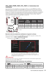
31 Vue d’ensemble des composants CPU_FAN1, PUMP_FAN1, SYS_FAN1~6 : Connecteurs de ventilateur Les connecteurs de ventilateur peuvent être utilisés en mode PWM (Pulse Width Modulation) et en mode DC. En mode PWM, les connecteurs fournissent une sortie de 12 V constante et ajustent la vitesse du venti...
Page 128 - JCI1 : Connecteur intrusion châssis; Utilisation du détecteur d’intrusion châssis; Réinitialisation de l’alerte intrusion châssis; Intrusion Configuration (Configuration intrusion châssis)
32 Vue d’ensemble des composants JCI1 : Connecteur intrusion châssis Ce connecteur est relié à un câble d’interrupteur intrusion châssis. Normal (défaut) Commencer l’activité instrusion châssis Utilisation du détecteur d’intrusion châssis 1. Reliez le connecteur JCI1 à l’interrupteur ou au capteur d...
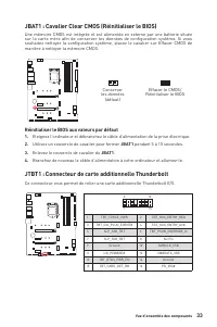
Page 129 - Réinitialiser le BIOS aux valeurs par défaut; JTBT1 : Connecteur de carte additionnelle Thunderbolt
33 Vue d’ensemble des composants JBAT1 : Cavalier Clear CMOS (Réinitialiser le BIOS) Une mémoire CMOS est intégrée et est alimentée en externe par une batterie située sur la carte mère afin de conserver les données de configuration système. Si vous souhaitez nettoyer la configuration système, placez...
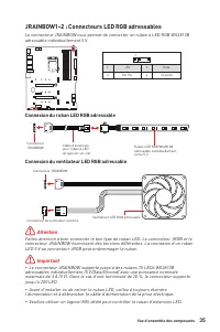
Page 131 - Attention; LED 5 V au connecteur JRGB peut endommager le ruban.; JRAINBOW1~2 : Connecteurs LED RGB adressables; adressable individuellement 5 V.; Connexion du ruban LED RGB adressable
35 Vue d’ensemble des composants 1 1 1 D +5V ⚠ Attention Faites attention à bien connecter le bon type de ruban LED. Le connecteur JRGB et le connecteur JRAINBOW fournissent des tensions différentes. La connexion d’un ruban LED 5 V au connecteur JRGB peut endommager le ruban. ⚠ Important ∙ Le connec...
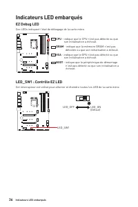
Page 132 - Ces LEDs indiquent l’état de débogage de la carte mère.; Indicateurs LED embarqués; - indique que le CPU n’est pas détecté ou que; - indique que la mémoire DRAM n’est pas; - indique que le GPU n’est pas détecté ou que; - indique que le périphérique de démarrage
36 Indicateurs LED embarqués EZ Debug LED Ces LEDs indiquent l’état de débogage de la carte mère. Indicateurs LED embarqués LED_SW1 : Contrôle EZ LED Cet interrupteur est utilisé pour allumer et éteindre toutes les LED de la carte mère. LED_SW1 LED_OFF LED_ON (Défaut) CPU - indique que le CPU n’est ...
Page 133 - Installer OS, Pilotes et MSI Center; Installer Windows® 10; Choisir quoi faire avec ce disque (Select to choose
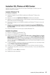
37 Installer OS, Pilotes et MSI Center Installer OS, Pilotes et MSI Center Veuillez vous référer au site www.msi.com pour télécharger et mettre à jour les derniers utilitaires et pilotes. Installer Windows® 10 1. Allumez l’ordinateur. 2. Insérez le disque ou la clé USB d’installation de Windows® 10 ...
Page 134 - Guide d’utilisation de MSI Center
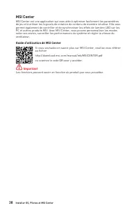
38 Installer OS, Pilotes et MSI Center MSI Center MSI Center est une application qui vous aide à optimiser facilement les paramètres de jeu et à utiliser les logiciels de création de contenu de manière intuitive. Elle vous permet également de contrôler et de synchroniser les effets de lumière LED su...
Page 135 - - cette carte mère supporte uniquement le
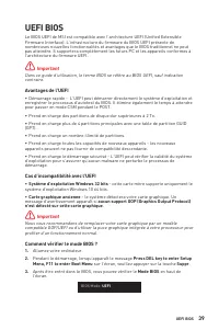
39 UEFI BIOS UEFI BIOS Le BIOS UEFI de MSI est compatible avec l’architecture UEFI (Unified Extensible Firmware Interface). L’infrastructure du firmware du BIOS UEFI présente de nombreuses nouvelles fonctionnalités et avantages que le BIOS traditionnel ne peut pas atteindre. Il supportera complèteme...
Page 136 - Configuration du BIOS; toujours garder les réglages par défaut; Entrer dans l’interface Setup du BIOS; Press DEL key to enter Setup; Touches de fonction; Guide d’utilisation du BIOS
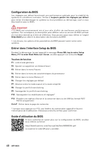
40 UEFI BIOS Configuration du BIOS Les réglages par défaut fournissent une performance optimale pour la stabilité du système en conditions normales. Veillez à toujours garder les réglages par défaut pour éviter d’endommager le système ou tout problème au démarrage, sauf si vous êtes familier avec le...
Page 137 - Réinitialiser le BIOS; Court-circuitez le cavalier; Clear CMOS; Mettre le BIOS à jour; Mettre le BIOS à jour avec M-FLASH; Del
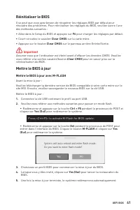
41 UEFI BIOS Réinitialiser le BIOS Il se peut que vous ayez besoin de récupérer les réglages BIOS par défaut pour résoudre des problèmes. Pour réinitialiser les réglages du BIOS, veuillez suivre l’une des méthodes suivantes : ∙ Allez dans le Setup du BIOS et appuyez sur F6 pour charger les réglages ...
Page 138 - Mettre le BIOS à jour avec MSI Center
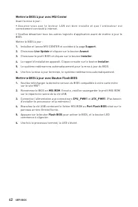
42 UEFI BIOS Mettre le BIOS à jour avec MSI Center Avant la mise à jour : ∙ Assurez-vous que le lecteur LAN est bien installé et que l’ordinateur est correctement connecté à internet. ∙ Veuillez désactiver tous les autres logiciels d’application avant de mettre à jour le BIOS.Mettre le BIOS à jour :...
Page 139 - Содержание; Безопасное использование продукции
1 Содержание Содержание Безопасное использование продукции ............................................................. 3 Уведомление о стойках для крепления материнской платы ............................. 4 Технические характеристики ...................................................................
Page 140 - Встроенные индикаторы
2 Содержание Встроенные индикаторы ................................................................................... 36 Индикаторы отладки EZ ...................................................................................... 36 LED_SW1: Переключатель для управления индикаторами EZ ...............
Page 142 - Уведомление о стойках для крепления материнской платы
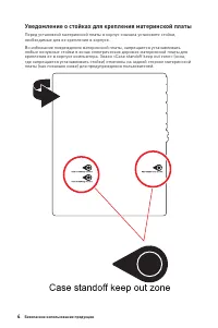
4 Безопасное использование продукции Уведомление о стойках для крепления материнской платы Перед установкой материнской платы в корпус сначала установите стойки, необходимые для ее крепления в корпусе. Во избежание повреждения материнской платы, запрещается устанавливать любые ненужные стойки в зона...
Page 143 - Технические характеристики; Процессор; Чипсет; Слоты расширения
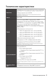
5 Технические характеристики Технические характеристики Процессор ∙ Поддержка процессоров Intel® Core™ 10-го поколения, Intel® Core™ 11-го поколения, Pentium® Gold и Celeron® * ∙ Процессорный сокет LGA1200 * Пожалуйста, обратитесь intel.com для получения дополнительной информации о совместимости. Чи...
Page 144 - Встроенная; Подключение
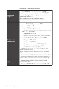
6 Технические характеристики Продолжение с предыдущей страницы Встроенная графика ∙ 1x порт HDMI 2.0b с поддержкой формата HDR, с поддержкой максимального разрешения 4K 60Гц*/** ∙ 1x порт DisplayPort 1.4, с поддержкой максимального разрешения 4K 60Гц*/** * Доступно для процессоров с интегрированной ...
Page 146 - Разъемы на плате
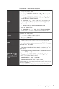
8 Технические характеристики Продолжение с предыдущей страницы Разъемы на плате ∙ 1x 24-контактный разъем питания ATX ∙ 1x 8-контактный разъем питания ATX 12В ∙ 1x 4-контактный разъем питания ATX 12В ∙ 1x 6-контактный разъем питания PCIE ∙ 6x разъемов SATA 6Гб/с ∙ 3x разъема M.2 (Ключ M) ∙ 1x порт U...
Page 147 - UEFI AMI BIOS
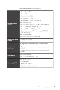
9 Технические характеристики Продолжение с предыдущей страницы Разъемы задней панели ∙ 1x порт DisplayPort ∙ 1x порт HDMI ∙ 1x кнопка Flash BIOS ∙ 2x порта USB 2.0 Type-A ∙ 4x порта USB 3.2 Gen1 5Гб/с Type-A ∙ 1x порт LAN I225V ∙ 1x порт LAN I219V (только для MAG Z590 TORPEDO) ∙ 1x порт USB 3.2 Gen ...
Page 148 - Продолжение с предыдущей страницы; Программное; Драйверы; Функции MSI
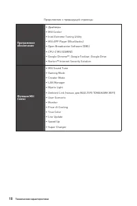
10 Технические характеристики Продолжение с предыдущей страницы Программное обеспечение ∙ Драйверы ∙ MSI Center ∙ Intel Extreme Tuning Utility ∙ MSI APP Player (BlueStacks) ∙ Open Broadcaster Software (OBS) ∙ CPU-Z MSI GAMING ∙ Google Chrome™, Google Toolbar, Google Drive ∙ Norton™ Internet Security...
Page 149 - Эксклюзивные
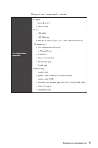
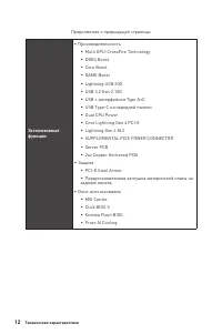
11 Технические характеристики Продолжение с предыдущей страницы Эксклюзивные функции ∙ Аудио ▪ Audio Boost 5 ▪ Sound Tune ∙ Сеть ▪ 2.5G LAN ▪ LAN Manager ▪ Intel Wi-Fi (только для MAG Z590 TOMAHAWK WIFI) ∙ Охлаждение ▪ Extended Heatsink Design ▪ M.2 Shield Frozr ▪ Pump Fan ▪ Smart Fan Control ▪ K7 t...
Page 151 - Комплект поставки; Материнская плата
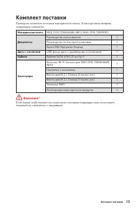
13 Комплект поставки Комплект поставки Проверьте комплект поставки материнской платы. В него должны входить следующие элементы: Материнская плата MAG Z590 TOMAHAWK WIFI/ MAG Z590 TORPEDO Документы Руководство пользователя 1 Руководство по быстрой установке 1 Карта MSI Программ Наград 1 Диск с утилит...
Page 152 - Задняя панель портов ввода/ вывода
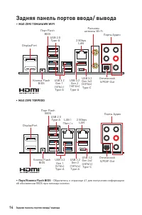
14 Задняя панель портов ввода/ вывода Задняя панель портов ввода/ вывода ∙ MAG Z590 TOMAHAWK WIFI ∙ Порт/Кнопка Flash BIOS - Обратитесь к странице 41 для получения информации об обновлении BIOS при помощи кнопки USB 3.2 Gen 2x2 (20Гб/с) Type-C USB 3.2 Gen 2x2 (20Гб/с) Type-C Кнопка Flash BIOS Кнопка...
Page 153 - Конфигурация портов Аудио; Порты Аудио; Таблица состояний индикатора порта LAN; изменения параметров звука, чтобы улучшить качество звука.
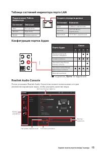
15 Задняя панель портов ввода/ вывода Конфигурация портов Аудио Порты Аудио Канал 2 4 6 8 Выход центральной колонки/ сабвуфера ● ● Тыловые колонки ● ● ● Линейный вход/ Выход боковых колонок ● Линейный выход/ Выход фронтальных колонок ● ● ● ● Микрофонный вход ( ●: подключен, Пусто : не подключен) Таб...
Page 154 - ∙ Выбор устройства; Автоматическое всплывающее диалоговое окно
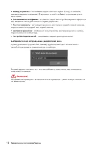
16 Задняя панель портов ввода/ вывода ∙ Выбор устройства – позволяет выбрать источник аудио выхода и изменить соответствующие параметры. Отмеченное устройство будет использоваться по умолчанию. ∙ Дополнительные эффекты – это список опций по настройке звуковых эффектов для входного и выходного сигнал...
Page 155 - Подключение наушников и микрофона
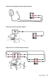
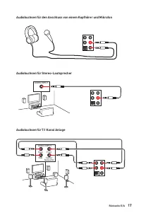
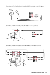
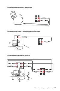
17 Задняя панель портов ввода/ вывода Подключение наушников и микрофона Подключение внешнего стерео усилителя (колонок) Подключение звуковой системы 7.1 AUDIO INPUT AUDIO INPUT Rear Front Side Center/ Subwoofer
Page 156 - Установка антенн; Отрегулируйте угол наклона антенны.
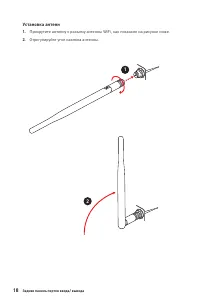
18 Задняя панель портов ввода/ вывода Установка антенн 1. Прикрутите антенну к разъему антенны WiFi, как показано на рисунке ниже. 2. Отрегулируйте угол наклона антенны. 1 2
Page 157 - Компоненты материнской платы
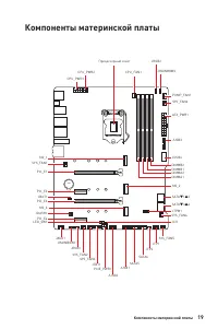
19 Компоненты материнской платы Компоненты материнской платы BAT1 SATA▼1▲2 JUSB3 JUSB4 ATX_PWR1 PUMP_FAN1 SYS_FAN6 JRAINBOW2 CPU_FAN1 DIMMB2 DIMMB1 DIMMA2 DIMMA1 SATA▼3▲4 SATA6 SATA5 Процессорный сокет CPU_PWR1 CPU_PWR2 JFP1 JFP2 SYS_FAN4 SYS_FAN5 JTPM1 JCI1 JBAT1 JUSB1 JUSB2 LED_SW1 PCIE_PWR1 SYS_F...
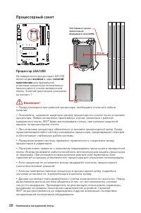
Page 158 - Процессорный сокет; выемки
20 Компоненты материнской платы ⚠ Внимание! ∙ Перед установкой или заменой процессора, необходимо отключить кабель питания. ∙ Пожалуйста, сохраните защитную крышку процессорного сокета после установки процессора. Любые возможные гарантийные случаи, связанные с работой материнской платы, MSI® будет р...
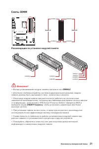
Page 159 - Слоты DIMM; Рекомендации по установке модулей памяти
21 Компоненты материнской платы Слоты DIMM DIMMA1 DIMMB1 Канал A Канал B DIMMA2 DIMMB2 Рекомендации по установке модулей памяти ⚠ Внимание! ∙ Всегда устанавливайте модуль памяти сначала в слот DIMMA2 . ∙ Для более стабильной работы системы в двухканальном режимах, модули памяти должны быть одинаково...
Page 160 - MSI Graphics Card Bolster; для поддержки веса графической карты; JAUD1: Разъем аудио передней панели
22 Компоненты материнской платы BAT1 PCI_E1~4: Слоты расширения PCIe PCI_E1 : PCIe 4.0 x16 (для CPU) PCI_E3 : PCIe 3.0 x4 (для чипсета Z590) PCI_E2 : PCIe 3.0 x1 (для чипсета Z590) PCI_E4 : P CIe 3.0 x1 (для чипсета Z590) ⚠ Внимание! ∙ При установке массивной видеокарты, необходимо использовать тако...
Page 161 - Удалите винты для радиатора M.2 SHIELD FROZR.; Видео Инструкция; Смотрите видео, чтобы узнать как
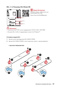
23 Компоненты материнской платы M2_1~3: Разъемы M.2 (Ключ M) Установка модуля M.2 1. Удалите винты для радиатора M.2 SHIELD FROZR. 2. Удалите M.2 SHIELD FROZR и снять защитную пленку с термоинтерфейса. M2_1 M2_2 M2_3 ⚠ Внимание! ∙ Технология Intel® RST только поддерживает PCIe M.2 SSD с UEFI ROM. ∙ ...
Page 162 - Пропустите шаг 3 и шаг 5, чтобы установить 22110 M.2 в разъем M2_1 или
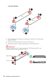
24 Компоненты материнской платы 3. При необходимости установите поставляемые стойки M.2 в соответствии с длиной M.2 SSD. 4. Вставьте M.2 SSD в разъем М.2 под углом 30 градусов. 5. Закрепите M.2 SSD с помощью прилагаемого винта 8.5H для M.2. ⚠ Внимание! Пропустите шаг 3 и шаг 5, чтобы установить 2211...
Page 163 - Установите на место радиатор M.2 SHIELD FROZR и закрепите его.
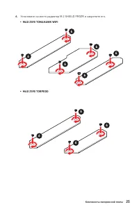
25 Компоненты материнской платы 6. Установите на место радиатор M.2 SHIELD FROZR и закрепите его. 6 6 6 6 6 6 6 6 ▪ MAG Z590 TORPEDO ▪ MAG Z590 TOMAHAWK WIFI 6 6
Page 164 - Таблица комбинации для слотов M.2 и SATA; Слот; PCIe (Разъем M2_1 будет доступен только при использовании; SATA; порту можно подключить одно устройство SATA.
26 Компоненты материнской платы Таблица комбинации для слотов M.2 и SATA Слот Доступные разъемы SATA M2_1 PCIe (Разъем M2_1 будет доступен только при использовании процессоров Intel® 11-го поколения) M2_2 PCIe SATA PCIe SATA PCIe SATA M2_3 PCIe PCIe SATA SATA ─ ─ SATA1 ✓ ✓ ✓ ✓ ✓ ✓ SATA2 ✓ ─ ✓ ─ ✓ ─ ...
Page 165 - расположенных на передней панели.; JDASH1: Разъем контроллера настройки
27 Компоненты материнской платы JFP1, JFP2: Разъемы передней панели Эти разъемы служат для подключения кнопок и светодиодных индикаторов, расположенных на передней панели. 1 2 10 9 + + + - - - - + Power LED HDD LED Reset Switch Reserved Power Switch JFP1 1 HDD LED + 2 Power LED + 3 HDD LED - 4 Power...
Page 166 - подключения всех кабелей питания к блоку питания АТХ.
28 Компоненты материнской платы 24 13 1 12 ATX_PWR1 1 +3.3V 13 +3.3V 2 +3.3V 14 -12V 3 Ground 15 Ground 4 +5V 16 PS-ON# 5 Ground 17 Ground 6 +5V 18 Ground 7 Ground 19 Ground 8 PWR OK 20 Res 9 5VSB 21 +5V 10 +12V 22 +5V 11 +12V 23 +5V 12 +3.3V 24 Ground 5 4 1 8 CPU_PWR1 1 Ground 5 +12V 2 Ground 6 +12...
Page 167 - контакты питания и земли.
29 Компоненты материнской платы JUSB3: Разъем USB 3.2 Gen 1 Данный разъем предназначен для подключения портов USB 3.2 Gen 1 5Гб/с на передней панели. ⚠ Внимание! Помните, что во избежание повреждений, необходимо правильно подключать контакты питания и земли. 1 10 11 20 1 Power 11 USB2.0+ 2 USB3_RX_D...
Page 168 - контакты VCC и земли.; JTPM1: Разъем модуля ТРМ
30 Компоненты материнской платы JUSB1~2: Разъемы USB 2.0 Данные разъемы предназначены для подключения портов USB 2.0 на передней панели. 1 2 10 9 1 VCC 2 VCC 3 USB0- 4 USB1- 5 USB0+ 6 USB1+ 7 Ground 8 Ground 9 No Pin 10 NC ⚠ Внимание! ∙ Помните, что во избежание повреждений, необходимо правильно под...
Page 169 - Переключение режимов работы и скорости вращения вентилятора; Назначение контактов разъема для подключения вентилятора; Разъем
31 Компоненты материнской платы CPU_FAN1, PUMP_FAN1, SYS_FAN1~6: Разъемы вентиляторов Разъемы вентиляторов можно разделить на два типа: с PWM (Pulse Width Modulation) управлением и управлением постоянным током. Разъемы вентиляторов с PWM управлением имеют контакт с постоянным напряжением 12В, а такж...
Page 170 - JCI1: Разъем датчика открытия корпуса; Использование датчика открытия корпуса
32 Компоненты материнской платы JCI1: Разъем датчика открытия корпуса К этому разъему подключается кабель от датчика открытия корпуса. Нормально (По умолчанию) Разрешить запись по событию открытия корпуса Использование датчика открытия корпуса 1. Подключите датчик открытия корпуса к разъему JCI1 . 2...
Page 171 - Сброс настроек BIOS до значений по умолчанию; JTBT1: Разъем для установки карты расширения
33 Компоненты материнской платы JBAT1: Джампер очистки данных CMOS (Сброс BIOS) На плате установлена CMOS память с питанием от батарейки для хранения данных о конфигурации системы. Для сброса конфигурации системы (очистки данных CMOS памяти), воспользуйтесь этим джампером. Сохранение данных (По умол...
Page 172 - обесточить систему и отключить кабель питания.; Подключение RGB светодиодных лент
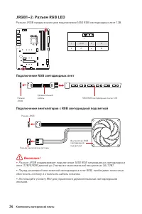
34 Компоненты материнской платы ⚠ Внимание! ∙ Разъем JRGB поддерживает подключение 5050 RGB непрерывных светодиодных лент (12В/G/R/B) длиной до 2 метров с максимальной мощностью 3А (12В). ∙ Перед установкой или заменой светодиодных лент RGB, необходимо полностью обесточить систему и отключить кабель...
Page 173 - светодиодных лент 5В к разъему JRGB приведет к их повреждению.; Подключение адресных RGB светодиодных лент
35 Компоненты материнской платы 1 1 1 D +5V ⚠ ВНИМАНИЕ! Не подключайте несовместимые с материнской платой светодиодные ленты. Разъем JRGB и разъем JRAINBOW имеют разное напряжение, и подключение светодиодных лент 5В к разъему JRGB приведет к их повреждению. ⚠ Внимание! ∙ Разъем JRAINBOW поддерживает...
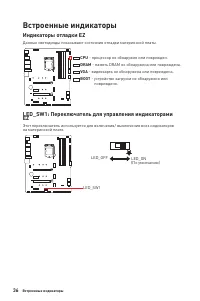
Page 174 - Индикаторы отладки EZ; - память DRAM не обнаружена или повреждена.; - видеокарта не обнаружена или повреждена.; - устройство загрузки не обнаружено или; LED_SW1: Переключатель для управления индикаторами; на материнской плате.
36 Встроенные индикаторы Индикаторы отладки EZ Данные светодиоды показывают состояния отладки материнской платы. CPU - процессор не обнаружен или поврежден. DRAM - память DRAM не обнаружена или повреждена. VGA - видеокарта не обнаружена или повреждена. BOOT - устройство загрузки не обнаружено или по...
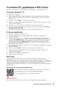
Page 175 - Установка ОС, драйверов и MSI Center; Установка Windows® 10; Установка драйверов; Инструкции по использованию MSI Center
37 Установка ОС, драйверов и MSI Center Установка ОС, драйверов и MSI Center Скачайте и обновите по следние утилиты и драйверы с сайта: www.msi.com Установка Windows® 10 1. Включите компьютер. 2. Вставьте диск Windows® 10 в привод для оптических дисков или вставьте в разъем USB компьютера USB флэш-д...
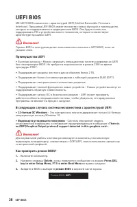
Page 176 - Преимущества UEFI; ∙ 32-битная ОС Windows; Как проверить режим BIOS?
38 UEFI BIOS UEFI BIOS MSI UEFI BIOS совместим с архитектурой UEFI (Unified Extensible Firmware Interface). Прошивка UEFI BIOS имеет множество новых функций и преимуществ, которые не поддерживаются традиционным BIOS. Она будет полностью поддерживать ПК и устройства нового поколения, которые соответс...
Page 177 - Настройка BIOS; всегда устанавливайте настройки по умолчанию; Вход в настройки BIOS; Функциональные клавиши; Инструкции по настройке BIOS
39 UEFI BIOS Настройка BIOS Настройки по умолчанию обеспечивают оптимальную производительность и стабильность системы при нормальных условиях. Если вы недостаточно хорошо знакомы с BIOS, всегда устанавливайте настройки по умолчанию . Это позволит избежать возможных повреждений системы, а также пробл...
Page 178 - Сброс BIOS; очистки данных CMOS; Обновление BIOS; Обновление BIOS при помощи M-FLASH; Yes
40 UEFI BIOS Сброс BIOS В некоторых ситуациях необходимо выполнить восстановление настроек BIOS до значений по умолчанию. Существует несколько способов сброса настроек: ∙ Войдите в BIOS и нажмите клавишу F6 для загрузки оптимизированных значений по умолчанию. ∙ Замкните джампер очистки данных CMOS н...
Page 179 - Обновление BIOS при помощи MSI Center; порт Flash BIOS
41 UEFI BIOS Обновление BIOS при помощи MSI Center Перед обновлением: ∙ Убедитесь, что драйвер локальной сети установлен и есть подключение к сети Интернет. ∙ Перед обновлением BIOS закройте все остальные приложения. Обновление BIOS: 1. Установите и запустите MSI CENTER, и затем перейдите на страниц...
Page 181 - Regulatory Notices; FCC Compliance Statement; クラスB情報技術装置
i Regulatory Notices Regulatory Notices FCC Compliance Statement Note: This equipment has been tested and found to comply with the limits for a Class B digital device, pursuant to part 15 of the FCC Rules. These limits are designed to provide reasonable protection against harmful interference in a r...
Page 182 - ii; WEEE (Waste Electrical and
ii Regulatory Notices WEEE (Waste Electrical and Electronic Equipment) Statement ENGLISH To protect the global environment and as an environmentalist, MSI must remind you that...Under the European Union (“EU”) Directive on Waste Electrical and Electronic Equipment, Directive 2002/96/EC, which takes ...
Page 183 - iii; India RoHS
iii Regulatory Notices gibi çöpe atılamayacak ve bu elektonik cihazların üreticileri, cihazların kullanım süreleri bittikten sonra ürünleri geri toplamakla yükümlü olacaktır. Avrupa Birliği’ne satılan MSI markalı ürünlerin kullanım süreleri bittiğinde MSI ürünlerin geri alınması isteği ile işbirliği...
Page 184 - iv; MS-7D08主板产品中有害物质的名称及含量
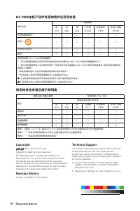
iv Regulatory Notices MS-7D08主板产品中有害物质的名称及含量 部件名称 有害物质 铅 (Pb) 汞 (Hg) 镉 (Cd) 六价铬 (Cr(VI)) 多溴联苯 (PBB) 多溴二苯醚 (PBDE) 印刷电路板组件* ╳ ○ ○ ○ ○ ○ 电池** ╳ ○ ○ ○ ○ ○ 外部信号连接头 ╳ ○ ○ ○ ○ ○ 线材 ╳ ○ ○ ○ ○ ○ 本表格依据 SJ/T 11364 的规定编制。○: 表示该有害物质在该部件所有均质材料中的含量均在 GB/T 26572 规定的限量要求以下。╳: 表示该有害物质至少在该部件的某一均质材料中的含量超出 GB/T 26572 规定...