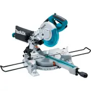
Page 2 - SPECIFICATIONS
2 ENGLISH ENGLISH (Original instructions) SPECIFICATIONS Model: XSL03 XSL04 XSL06 Blade diameter 255 mm (10″) Hole diameter 15.88 mm (5/8″) Max. kerf thickness of the saw blade 3.2 mm (1/8″) Max. miter angle Right 60°, Left 60° Max. bevel angle Right 48°, Left 48° No load speed (RPM) 4,400 /min Lase...
Page 3 - SAFETY WARNINGS; tion manual before operating tool.; General power tool safety warnings; Save all warnings and instruc-
3 ENGLISH SAFETY WARNINGS For your own safety, read instruc- tion manual before operating tool. Save it for future reference. General power tool safety warnings WARNING: Read all safety warnings, instruc- tions, illustrations and specifications provided with this power tool. Failure to follow all in...
Page 4 - Safety instructions for mitre saws
4 ENGLISH 5. Maintain power tools and accessories. Check for misalignment or binding of moving parts, breakage of parts and any other condition that may affect the power tool’s operation. If dam- aged, have the power tool repaired before use. Many accidents are caused by poorly maintained power tool...
Page 6 - Symbols; Important safety instructions for
6 ENGLISH 10. While making a slide cut, KICKBACK can occur. KICKBACK occurs when the blade binds in the workpiece during a cutting oper- ation and the saw blade is driven rapidly towards the operator. Loss of control and seri- ous personal injury can result. If blade begins to bind during a cutting ...
Page 7 - Tips for maintaining maximum; SAVE THESE INSTRUCTIONS.
7 ENGLISH 11. Follow your local regulations relating to dis- posal of battery. SAVE THESE INSTRUCTIONS. CAUTION: Only use genuine Makita batteries. Use of non-genuine Makita batteries, or batteries that have been altered, may result in the battery bursting causing fires, personal injury and damage. ...
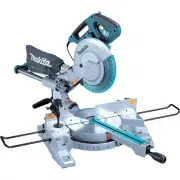
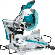
Page 8 - PARTS DESCRIPTION
8 ENGLISH PARTS DESCRIPTION 10 1112 14 15 3 2 45 8 7 9 13 6 1 16 17 18 20 21 22 19 1 Slide pole 2 Stopper pin (for carriage sliding) 3 Vertical vise 4 Releasing button (for right side bevel angle) 5 Holder 6 Turn base 7 Pointer (for miter angle) 8 Miter angle scale 9 Kerf board 10 Blade case 11 Adju...
Page 10 - INSTALLATION; Installing the grip; Installing the dust extraction hose; Bench mounting
10 ENGLISH INSTALLATION Installing the grip Screw the threaded shaft of the grip into the turn base. 1 2 ► 1. Grip 2. Turn base Installing the dust extraction hose Connect the dust extraction hose to the tool as illustrated. Make sure that the elbow and the sleeve fit properly to the ports of the to...
Page 11 - Installing or removing battery; Tool / battery protection system; Overdischarge protection
11 ENGLISH FUNCTIONAL DESCRIPTION WARNING: Always be sure that the tool is switched off and the battery cartridge is removed before adjusting or checking the functions on the tool. Failure to switch off and remove the battery cartridge may result in serious personal injury from accidental start-up. ...
Page 12 - Automatic speed change function
12 ENGLISH Battery indicator status Remaining battery capacity On Off Blinking 50% to 100% 20% to 50% 0% to 20% Charge the battery Indicating the remaining battery capacity Only for battery cartridges with the indicator 1 2 ► 1. Indicator lamps 2. Check button Press the check button on the battery c...
Page 13 - Kerf boards
13 ENGLISH In the interest of your personal safety, always maintain the blade guard in good condition. Any irregular opera - tion of the blade guard should be corrected immediately. Check to assure spring loaded return action of guard. WARNING: Never use the tool if the blade guard or spring are dam...
Page 14 - Stopper arm
14 ENGLISH Maintaining maximum cutting capacity This tool is factory adjusted to provide the maximum cutting capacity for a 255 mm (10") saw blade. When installing a new blade, always check the lower limit position of the blade and if necessary, adjust it as follows: First, remove the batteries....
Page 16 - Slide lock
16 ENGLISH 3. Match the pointer with your desired angle on the scale by moving the carriage then tighten the knob. 1 2 ► 1. Bevel angle scale 2. Pointer To tilt the carriage to the right, tilt the carriage to the left slightly and then tilt it to the right while pressing down the releasing button. 1...
Page 18 - ASSEMBLY; Hex wrench storage
18 ENGLISH 1 ► 1. Adjusting screw 1. Loosen the adjusting screw by turning it counterclockwise. 2. With the adjusting screw loosened, slide the adjusting screw to the right or left as far as it goes. 3. Tighten the adjusting screw firmly at the position where it stops sliding. NOTE: Laser line is fa...
Page 19 - Removing the blade; Installing the blade
19 ENGLISH 2 1 3 ► 1. Unlocked position 2. Locked position 3. Stopper pin Removing the blade Loosen the hex bolt holding the center cover using the hex wrench. Raise the blade guard and center cover. 3 1 2 ► 1. Center cover 2. Hex wrench 3. Blade guard Press the shaft lock to lock the spindle and us...
Page 21 - Vertical vise
21 ENGLISH Securing workpiece WARNING: It is extremely important to always secure the workpiece correctly with the proper type of vise or crown molding stoppers. Failure to do so may result in serious personal injury and cause damage to the tool and/or the workpiece. WARNING: After a cutting operati...
Page 22 - Horizontal vise; Holders
22 ENGLISH 1 2 3 4 ► 1. Vise arm 2. Vise rod 3. Clamping screw 4. Vise knob The vertical vise can be installed in two positions on either the left or right side of the base. Insert the vise rod into the hole in the base. Position the vise arm according to the thickness and shape of the workpiece and...
Page 23 - OPERATION; Press cutting
23 ENGLISH OPERATION WARNING: Make sure the blade is not con- tacting the workpiece, etc. before the switch is turned on. Turning the tool on with the blade in contact with the workpiece may result in kickback and serious personal injury. WARNING: After a cutting operation, do not raise the blade un...
Page 25 - Compound cutting; Cutting crown and cove moldings
25 ENGLISH 8. When the cut is completed, switch off the tool and wait until the blade has come to a complete stop before returning the blade to its fully elevated position. Compound cutting Compound cutting is the process in which a bevel angle is made at the same time in which a miter angle is bein...
Page 26 - In the case of right bevel cut
26 ENGLISH Table (A) – Molding position in the figure Bevel angle Miter angle 52/38° type 45° type 52/38° type 45° type For inside corner (a) Left 33.9° Left 30° Right 31.6° Right 35.3° (b) Left 31.6° Left 35.3° For outside corner (c)(d) Right 31.6° Right 35.3° Table (B) – Molding position in the fi...
Page 27 - Miter and Bevel Angle Settings
27 ENGLISH Miter and Bevel Angle Settings Wall to Crown Molding Angle: 52°/38° 30.1 29.7 29.4 29.0 28.7 28.3 28.0 27.6 27.2 26.9 26.5 26.1 25.8 25.4 25.0 24.7 24.3 23.9 23.6 23.2 22.8 22.5 22.1 21.7 21.3 21.0 20.6 20.2 19.8 19.5 19.1 18.7 18.3 17.9 17.6 17.2 16.8 16.4 16.0 15.6 26.9 26.5 26.1 25.7 2...
Page 29 - Crown molding stopper
29 ENGLISH Crown molding stopper Optional accessory Crown molding stoppers allow easier cuts of crown molding without tilting the saw blade. Install them on the turn base as shown in the figures. At right 45° miter angle 1 2 34 ► 1. Crown molding stopper L 2. Crown molding stop- per R 3. Turn base 4...
Page 31 - What you can do with the wireless
31 ENGLISH WIRELESS ACTIVATION FUNCTION For XSL04 only What you can do with the wireless activation function The wireless activation function enables clean and com - fortable operation. By connecting a supported vacuum cleaner to the tool, you can run the vacuum cleaner automatically along with the ...
Page 32 - Tool registration for the vacuum
32 ENGLISH 1 2 3 ► 1. Wireless unit 2. Hook 3. Lid After removing the wireless unit, keep it in the supplied case or a static-free container. NOTICE: Always use the hooks on the back of the lid when removing the wireless unit. If the hooks do not catch the wireless unit, close the lid completely and...
Page 34 - Description of the wireless activation lamp status
34 ENGLISH Description of the wireless activation lamp status 1 ► 1. Wireless activation lamp The wireless activation lamp shows the status of the wireless activation function. Refer to the table below for the meaning of the lamp status. Status Wireless activation lamp Description Color On Blinking ...
Page 36 - Troubleshooting for wireless activation function
36 ENGLISH Troubleshooting for wireless activation function Before asking for repairs, conduct your own inspection first. If you find a problem that is not explained in the manual, do not attempt to dismantle the tool. Instead, ask Makita Authorized Service Centers, always using Makita replace - men...
Page 37 - MAINTENANCE; Adjusting the cutting angle
37 ENGLISH State of abnormality Probable cause (malfunction) Remedy The vacuum cleaner does not run along with the switch operation of the tool. The wireless unit is not installed into the tool. The wireless unit is improperly installed into the tool. Install the wireless unit correctly. The termina...
Page 38 - Bevel angle; ° bevel angle
38 ENGLISH 1 ► 1. Triangular rule Bevel angle 0° bevel angle Push the carriage toward the guide fence and lock the sliding movement by the stopper pin. Lower the handle fully and lock it in the lowered position by the stopper pin and then loosen the knob. Turn the 0° adjusting bolt two or three revo...
Page 39 - Adjusting the laser line position
39 ENGLISH 1 2 ► 1. Left 45° adjusting bolt 2. Right 45° adjusting bolt Adjusting the laser line position For XSL04, XSL06 only WARNING: The batteries must be installed while adjusting the laser line. Take extra care not to switch on the tool during adjustment. Accidental start up of the tool may re...
Page 40 - OPTIONAL; MAKITA LIMITED ONE YEAR; Warranty Policy
40 ENGLISH 7. Slide the adjusting screw to the position that the laser line comes onto the cutting line and then tighten. NOTE: The movable range of laser line is factory adjusted within 1 mm (0.04") from the side surface of blade. Cleaning the laser light lens For XSL04, XSL06 only The laser li...
Page 41 - ESPECIFICACIONES
41 ESPAÑOL ESPAÑOL (Instrucciones originales) ESPECIFICACIONES Modelo: XSL03 XSL04 XSL06 Diámetro del disco 255 mm (10″) Diámetro del orificio 15,88 mm (5/8″) Ancho de corte máx. del disco de la sierra 3,2 mm (1/8″) Ángulo de inglete máximo Derecho 60°, Izquierdo 60° Ángulo de bisel máximo Derecho 4...
Page 42 - Advertencias generales de
42 ESPAÑOL ADVERTENCIAS DE SEGURIDAD Por su propia seguridad lea el manual de instrucciones Antes de utilizar la herramienta. Conserve las instrucciones para referencia en el futuro. Advertencias generales de seguridad para herramientas eléctricas ADVERTENCIA: Lea todas las advertencias de seguridad...
Page 46 - Símbolos; Instrucciones importantes de; GUARDE ESTAS
46 ESPAÑOL 19. Pare la operación inmediatamente si nota algo anormal. 20. No intente bloquear el gatillo en la posición activada. 21. Utilice los accesorios recomendados en este manual. El uso de accesorios inapropiados tales como discos abrasivos podría ocasionar lesiones. 22. Algunos materiales co...
Page 47 - Consejos para alargar al máximo; Instrucciones importantes
47 ESPAÑOL PRECAUCIÓN: Utilice únicamente baterías originales de Makita. El uso de baterías no origina- les de Makita, o de baterías alteradas, puede ocasio- nar que las baterías exploten causando un incendio, lesiones personales y daños. Asimismo, esto inva - lidará la garantía de Makita para la he...
Page 48 - DESCRIPCIÓN DE LAS PIEZAS
48 ESPAÑOL DESCRIPCIÓN DE LAS PIEZAS 10 1112 14 15 3 2 45 8 7 9 13 6 1 16 17 18 20 21 22 19 1 Soporte de corredera 2 Clavija de retención (para el deslizamiento del carro) 3 Prensa vertical 4 Botón de liberación (para el ángulo de bisel del lado derecho) 5 Soporte 6 Base giratoria 7 Marcador (para e...
Page 50 - INSTALACIÓN; Instalación de la perilla
50 ESPAÑOL INSTALACIÓN Instalación de la perilla Atornille el eje roscado de la perilla en la base giratoria. 1 2 ► 1. Perilla 2. Base giratoria Instalación de la manguera de extracción de polvo Conecte la manguera de extracción de polvo a la herra - mienta tal como se muestra en la ilustración. Ase...
Page 51 - Instalación o extracción del; Sistema de protección para la; Protección contra sobredescarga
51 ESPAÑOL DESCRIPCIÓN DEL FUNCIONAMIENTO ADVERTENCIA: Asegúrese siempre de que la herramienta esté apagada y el cartucho de batería haya sido extraído antes de realizar cual- quier ajuste o revisión del funcionamiento de la herramienta. El no apagar y extraer el cartucho de batería puede provocar l...
Page 52 - Función de cambio de velocidad; Protector del disco
52 ESPAÑOL Estado del indicador de batería Capacidad restante de la batería Encendido Apagado Parpadeando 50% a 100% 20% a 50% 0% a 20% Cargar la batería Indicación de la capacidad restante de la batería Únicamente para cartuchos de batería con el indicador 1 2 ► 1. Luces indicadoras 2. Botón de ver...
Page 53 - Paneles de corte
53 ESPAÑOL ADVERTENCIA: Nunca inhabilite o quite el protector del disco, ni el resorte que lo fija. Un disco expuesto como resultado de inhabilitar el protector puede causar graves lesiones personales durante la operación. Con el fin de garantizar su seguridad personal, man - tenga siempre el protec...
Page 54 - Mantenimiento de la capacidad
54 ESPAÑOL 1 2 3 4 6 5 ► 1. Corte en bisel izquierdo 2. Corte recto 3. Corte en bisel derecho 4. Disco de la sierra 5. Dientes del disco 6. Panel de corte Primero, retire las baterías. Afloje todos los tornillos (2 de cada lado a la izquierda y la derecha) que fijan los paneles de corte hasta que és...
Page 56 - Ajuste del ángulo de bisel
56 ESPAÑOL Gire la perilla en el sentido inverso al de las manecillas del reloj para desbloquear la base giratoria. Gire la peri - lla mientras presiona hacia abajo la palanca de bloqueo para mover la base giratoria. Alinee el marcador con su ángulo deseado en la escala y luego apriete la perilla. N...
Page 58 - Freno eléctrico; Función eléctrica
58 ESPAÑOL 1 2 3 ► 1. Gatillo interruptor 2. Botón de desbloqueo 3. Orificio para el candado El botón de desbloqueo es suministrado para evitar jalar accidentalmente el gatillo interruptor. Para encen - der la herramienta, presione el botón de desbloqueo y jale el gatillo interruptor. Para detenerla...
Page 59 - MONTAJE; Almacenamiento de la llave Allen
59 ESPAÑOL Alineación de la línea de láser Alinee la línea de corte en su pieza de trabajo con la línea de láser. A B A) Cuando desee obtener el tamaño correcto del lado izquierdo de la pieza de trabajo, cambie la línea de láser a la izquierda del disco. B) Cuando desee obtener el tamaño correcto de...
Page 62 - Guías laterales
62 ESPAÑOL Aseguramiento de la pieza de trabajo ADVERTENCIA: Es sumamente importante asegurar siempre la pieza de trabajo de manera correcta usando un tipo adecuado de prensa o topes para moldura de corona. El no hacerlo podría ocasionar lesiones personales graves y causar daños a la herramienta y/o...
Page 63 - Prensa vertical; Prensa horizontal; Soportes
63 ESPAÑOL Prensa vertical ADVERTENCIA: La pieza de trabajo deberá estar firmemente sujetada contra la base giratoria y la guía lateral con la prensa durante todas las operaciones. Si la pieza de trabajo no queda debi - damente asegurada contra la guía, el material podría desplazarse durante la oper...
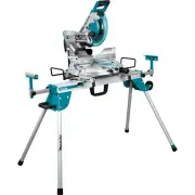
Page 64 - OPERACIÓN; Corte con prensa
64 ESPAÑOL Para sostener piezas de trabajo largas de forma hori - zontal, la herramienta cuenta con soportes a ambos lados. Afloje los tornillos y extienda los soportes a una longitud adecuada para sostener la pieza de trabajo. Luego apriete los tornillos. 1 2 ► 1. Soporte 2. Tornillo OPERACIÓN ADVE...
Page 66 - Corte compuesto; Corte de molduras corona y
66 ESPAÑOL 6. Encienda la herramienta sin que el disco haga contacto alguno y espere hasta que ésta alcance la velocidad máxima. 7. Baje suavemente la empuñadura hasta la posición completamente hacia abajo aplicando presión parale - lamente con el disco y empuje el carro hacia la guía lateral para c...
Page 67 - En caso de corte en bisel izquierdo
67 ESPAÑOL En caso de corte en bisel izquierdo (a) (b) (c) (d) 1 2 1. Rincón interno 2. Rincón externo Tabla (A) – Posición de la moldura en la figura Ángulo de bisel Ángulo de inglete Tipo de 52/38° Tipo de 45° Tipo de 52/38° Tipo de 45° Para rincón interno (a) Izquierda 33,9° Izquierda 30° Derecha...
Page 68 - Ajustes del ángulo de inglete y de bisel
68 ESPAÑOL Ajustes del ángulo de inglete y de bisel De la pared al ángulo de la moldura corona: 52°/38° 30.1 29.7 29.4 29.0 28.7 28.3 28.0 27.6 27.2 26.9 26.5 26.1 25.8 25.4 25.0 24.7 24.3 23.9 23.6 23.2 22.8 22.5 22.1 21.7 21.3 21.0 20.6 20.2 19.8 19.5 19.1 18.7 18.3 17.9 17.6 17.2 16.8 16.4 16.0 1...
Page 70 - Tope para moldura de corona
70 ESPAÑOL Tope para moldura de corona Accesorio opcional Los topes para moldura de corona permiten cortar más fácilmente una moldura de corona sin tener que inclinar el disco de la sierra. Instálelos en la base giratoria tal como se muestra en las ilustraciones. A un ángulo de inglete de 45° derech...
Page 72 - FUNCIÓN DE; Lo que puede hacer con la función
72 ESPAÑOL PRECAUCIÓN: Asegúrese siempre de que todas las partes móviles se encuentran fijas antes de transportar la herramienta. Durante el transporte de la herramienta, el desplazamiento o desliza- miento de alguna de sus partes podría provocar la pérdida de control o equilibrio ocasionando lesion...
Page 73 - Registro de la herramienta para la
73 ESPAÑOL 1 2 3 ► 1. Unidad inalámbrica 2. Gancho 3. Tapa Una vez extraída la unidad inalámbrica, guárdela en el estuche suministrado o en un contenedor libre de elec- tricidad estática. AVISO: Use siempre los ganchos en la parte posterior de la tapa cuando extraiga la unidad inalámbrica. Si los ga...
Page 78 - MANTENIMIENTO; Ajuste del ángulo de corte
78 ESPAÑOL Estado de la anomalía Causa probable (avería) Remedio La aspiradora no funciona junto con el interruptor de la herramienta. La unidad inalámbrica no está instalada en la herramienta. La unidad inalámbrica está instalada incorrectamente en la herramienta. Instale la unidad inalámbrica corr...
Page 79 - Ángulo de bisel; Ángulo de bisel de 0°
79 ESPAÑOL 1 ► 1. Regla triangular Ángulo de bisel Ángulo de bisel de 0° Empuje el carro hacia la guía lateral y bloquee el movi - miento de deslizamiento usando la clavija de retención. Baje la empuñadura por completo y bloquéela en la posición hacia abajo usando la clavija de retención y luego afl...
Page 81 - Limpieza del lente de luz láser; Luego del uso; ACCESORIOS
81 ESPAÑOL Ajuste de la línea de láser del lado derecho del disco 4 5 1 2 3 ► 1. Tornillo de ajuste 2. Tornillo de ajuste de rango 3. Llave hexagonal 4. Línea de láser 5. Disco de la sierra 7. Deslice el tornillo de ajuste a la posición en la que la línea de láser se dirija a la línea de corte y lue...
Page 82 - Ésta Garantía no aplica para México
82 ESPAÑOL GARANTÍA LIMITADA DE UN AÑO DE MAKITA Ésta Garantía no aplica para México Política de garantía Cada herramienta Makita es inspeccionada y probada exhaustivamente antes de salir de la fábrica. Se garan- tiza que está libre de defectos de mano de obra y mate- riales por el período de UN AÑO...
Page 84 - WARNING; productos químicos son:; Makita Corporation
Some dust created by power sanding, sawing, grinding, drilling, and other construction activities contains chemicals known to the State of California to cause cancer, birth defects or other reproductive harm. Some examples of these chemicals are: • lead from lead-based paints, • crystalline silica f...


 Makita GSL02Z
User Manual
Makita GSL02Z
User Manual
 Makita GSL03Z
User Manual
Makita GSL03Z
User Manual
 Makita GSL04M1
User Manual
Makita GSL04M1
User Manual
 Makita LH1040
User Manual
Makita LH1040
User Manual
 Makita LH1040F
User Manual
Makita LH1040F
User Manual
 Makita LS0815F
User Manual
Makita LS0815F
User Manual
 Makita LS1018
User Manual
Makita LS1018
User Manual
 Makita LS1018A-93681
User Manual
Makita LS1018A-93681
User Manual
 Makita LS1019L
User Manual
Makita LS1019L
User Manual
 Makita LS1019LX
User Manual
Makita LS1019LX
User Manual
 Makita LS1040
User Manual
Makita LS1040
User Manual
 Makita LS1219L
User Manual
Makita LS1219L
User Manual
 Makita LS1219LX
User Manual
Makita LS1219LX
User Manual
 Makita LS1221
User Manual
Makita LS1221
User Manual
 Makita MLS100
User Manual
Makita MLS100
User Manual
 Makita XSL02Z
User Manual
Makita XSL02Z
User Manual
 Makita XSL05Z
User Manual
Makita XSL05Z
User Manual