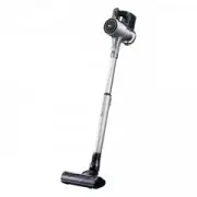
LG V-C7050NT - Manuals
LG V-C7050NT Vacuum – Manual in PDF format online.
Manuals:
Manual LG V-C7050NT


Summary
2 CONTENTS SAFETY PRECAUTIONS ......................................................................................................................... 3 CAUTIONS ............................................................................................................................................
5 • Almost all the parts of this vacuum cleaner can be disassembled with a screw driver and each connectingcomponent easily fits each other.Disassemble one by one referring to the exploded view. • If possible, don’t disassemble except for the necessary parts. It is not necessary to disassemblethe pa...
6 TROUBLE SHOOTING 1. SWITCH ON BUT MOTOR DOES NOT TURN 2. SWITCH ON, MOTOR DOES NOT TURN BUT BUZZES CHECKING CHECK THE POWERSOURCE The fuse is melt down in thecoverknife switch. Exchange the fuse. Poor plug insertion Insert again. Power cord cut Repair or exchange. Interior lead wire cut Exchange t...
LG Vacuums Manuals
-
 LG A931KWM
User Manual
LG A931KWM
User Manual
-
 LG A9ESSENTIAL
User Manual
LG A9ESSENTIAL
User Manual
-
 LG A9K-AQUA
User Manual
LG A9K-AQUA
User Manual
-
 LG A9K-EVOLVE
User Manual
LG A9K-EVOLVE
User Manual
-
 LG A9MASTER2X
User Manual
LG A9MASTER2X
User Manual
-
 LG A9MULTI2X CordZero
User Manual
LG A9MULTI2X CordZero
User Manual
-
 LG A9N-CORE
User Manual
LG A9N-CORE
User Manual
-
 LG A9NEOMAX
User Manual
LG A9NEOMAX
User Manual
-
 LG A9N-MULTI
User Manual
LG A9N-MULTI
User Manual
-
 LG A9PETNBED2X
User Manual
LG A9PETNBED2X
User Manual
-
 LG CordZero A9ESSENTIAL
User Manual
LG CordZero A9ESSENTIAL
User Manual
-
 LG CordZero A9-LITE
User Manual
LG CordZero A9-LITE
User Manual
-
 LG CordZero A9MASTER2X
User Manual
LG CordZero A9MASTER2X
User Manual
-
 LG CordZero A9MULTICARE
User Manual
LG CordZero A9MULTICARE
User Manual
-
 LG CordZero A9N-Core
User Manual
LG CordZero A9N-Core
User Manual
-
 LG FVD3700
User Manual
LG FVD3700
User Manual
-
 LG Kompressor Plus VK8828HQ
User Manual
LG Kompressor Plus VK8828HQ
User Manual
-
 LG Kompressor VC83209UHAV
User Manual
LG Kompressor VC83209UHAV
User Manual
-
 LG KV-PRO
User Manual
LG KV-PRO
User Manual
-
 LG MVK71187HU
User Manual
LG MVK71187HU
User Manual