Honeywell TH3110U2008 - Manuals
Honeywell TH3110U2008 – Manual, Installation Manual in PDF format online.
Manuals:
Manual Honeywell TH3110U2008


Summary
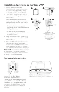
2 Power options Insert AA batteries for primary or backup power. UWP Mounting System installation Use 3x supplied screws (#8 1-1/2” (38 mm) for red anchors and #6 1-1/2” (38 mm) for yellow anchors) 1. Before starting, turn the power off at the breaker box or switch. Open package to find the UWP. See...
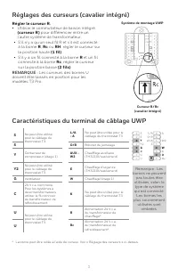
3 UWP Wiring terminal designations S Not used for T3 thermostat. L/A - A Not used for T3 thermostat. S O/B Changeover valve Y Compressor contactor (stage 1) AUX - W2 Auxiliary heat (TH3210U only) Y2 Not used for T3 thermostat. E Emergency heat (TH3210U only) G Fan W Heat (stage 1) C 24VAC common. Fo...
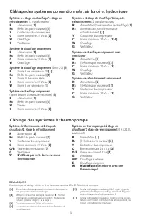
4 1H/1C System (1 transformer) R Power [1] Rc [R+Rc joined by Slider Tab] [2] Y Compressor contactor C 24VAC common [3] W Heat G Fan Heat-only System R Power [1] Rc [R+Rc joined by Slider Tab] [2] C 24VAC common [3] W Heat Heat-only System (Series 20) [5] R Series 20 valve terminal “R” [1] Rc [R+Rc ...
Installation Manual Honeywell TH3110U2008


Summary
2 Power options Insert AA batteries for primary or backup power. UWP Mounting System installation Use 3x supplied screws (#8 1-1/2” (38 mm) for red anchors and #6 1-1/2” (38 mm) for yellow anchors) 1. Before starting, turn the power off at the breaker box or switch. Open package to find the UWP. See...
3 UWP Wiring terminal designations S Not used for T3 thermostat. L/A - A Not used for T3 thermostat. S O/B Changeover valve Y Compressor contactor (stage 1) AUX - W2 Auxiliary heat (TH3210U only) Y2 Not used for T3 thermostat. E Emergency heat (TH3210U only) G Fan W Heat (stage 1) C 24VAC common. Fo...
4 1H/1C System (1 transformer) R Power [1] Rc [R+Rc joined by Slider Tab] [2] Y Compressor contactor C 24VAC common [3] W Heat G Fan Heat-only System R Power [1] Rc [R+Rc joined by Slider Tab] [2] C 24VAC common [3] W Heat Heat-only System (Series 20) [5] R Series 20 valve terminal “R” [1] Rc [R+Rc ...
Honeywell Manuals
-
 Honeywell DT8050A
Installation Manual
Honeywell DT8050A
Installation Manual
-
 Honeywell DT8050
Manual
Honeywell DT8050
Manual
-
Honeywell DT8050
User Manual
-
 Honeywell TPFIT25WK
User Manual
Honeywell TPFIT25WK
User Manual
-
Honeywell TPFIT32WK
User Manual
-
 Honeywell 24DX47
User Manual
Honeywell 24DX47
User Manual
-
 Honeywell TPFIT50PWK
User Manual
Honeywell TPFIT50PWK
User Manual
-
 Honeywell TPFIT50WK
User Manual
Honeywell TPFIT50WK
User Manual
-
Honeywell TPFIT50AWK
User Manual
-
Honeywell TPFIT50APWK
User Manual
-
 Honeywell 00010
User Manual
Honeywell 00010
User Manual
-
 Honeywell TP70AWKNR
User Manual
Honeywell TP70AWKNR
User Manual
-
 Honeywell PC42E-T
User Manual
Honeywell PC42E-T
User Manual
-
 Honeywell H3UF*
User Manual
Honeywell H3UF*
User Manual
-
Honeywell TP70PWKNR
User Manual
-
 Honeywell HPA3100B
User Manual
Honeywell HPA3100B
User Manual
-
 Honeywell PM65
User Manual
Honeywell PM65
User Manual
-
 Honeywell T6 PRO Z-WAVE PROGRAMMABLE THERMOSTAT
Manual
Honeywell T6 PRO Z-WAVE PROGRAMMABLE THERMOSTAT
Manual
-
Honeywell T6 PRO Z-WAVE PROGRAMMABLE THERMOSTAT
User Manual
-
 Honeywell E3539N
User Manual
Honeywell E3539N
User Manual