Honeywell TH3110U2008 - Manual
Honeywell TH3110U2008 – Manual, read for free online in PDF format. We hope this helps you resolve any issues you may have. If you have further questions, please contact us through the contact form.


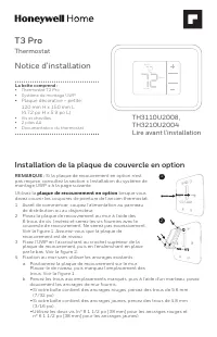
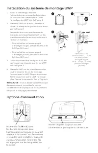
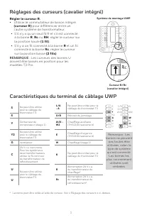
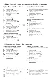
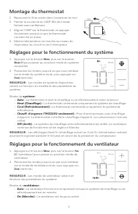
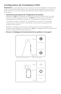
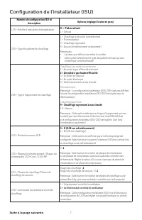
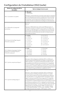
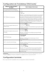
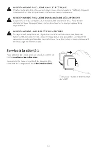


Table of Contents:
- Page 2 – Drill holes at marked positions, and
- Page 3 – UWP Wiring terminal designations; terminals may be
- Page 4 – Wiring heat pump systems
- Page 5 – System; Fan operation settings; Fan
- Page 6 – Select System Setup options.; Press; Edit; . The thermostat will save and exit to the home screen.
- Page 7 – ISU Setup Number and Description; = High Efficiency Gas Forced Air
- Page 9 – Once you have cycled through all of the System Setup numbers, press; Done; to save and exit to the home screen.; Setup Complete
- Page 10 – Mode
- Page 11 – Customer assistance; Pull to remove the thermostat; CAUTION: MERCURY NOTICE; damage, avoid cycling the compressor quickly.; CAUTION: ELECTRICAL HAZARD; beginning installation.
- Page 13 – Lire avant l’installation; • Plaque décorative – petite; Notice d’installation; Thermostat; plaque de recouvrement en option; Installation de la plaque de couvercle en option
- Page 15 – Caractéristiques du terminal de câblage UWP; Régler le curseur R.
- Page 16 – Câblage des systèmes conventionnels : air forcé et hydronique; Câblage des systèmes à thermopompe
- Page 17 – Réglages pour le fonctionnement du ventilateur; Menu
- Page 18 – Sélectionnez les options de configuration du système.; Passez à « Réglages du fonctionnement du système » à la page 6.
- Page 19 – = Air pulsé à gaz haute efficacité; = Chauffage rayonnant à eau chaude
- Page 21 – Configuration terminée
- Page 23 – Service à la clientèle; MISE EN GARDE : AVIS RELATIF AU MERCURE
- Page 25 – Instrucciones para la; Termostato; Instalación de la placa de cubierta opcional; placa de cubierta opcional
- Page 26 – Opciones de suministro eléctrico
- Page 27 – Designaciones de los terminales del cableado del UWP; Configure la lengüeta del control
- Page 28 – Cableado de sistemas convencionales: aire forzado e hidrónico; No utilizar este terminal para las; Cableado de sistemas de bomba de calor
- Page 29 – Montaje del termostato; Ajustes de funcionamiento del sistema
- Page 30 – Presione; guardará los cambios y se mostrará la pantalla de inicio.; Continúe con”Configuración por el instalador (ISU)” en la página 6.
- Page 31 – = El termostato controla el ventilador; Continúa en la página siguiente.
- Page 33 – Configuración del sistema completa
- Page 35 – Asistencia al cliente; PRECAUCIÓN: AVISO SOBRE EL MERCURIO
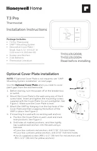
Package Includes:
• T3 Pro Thermostat
• UWP™ Mounting System
• Decorative Cover Plate –
Small; Size 4.72” H X 5.9” W
(120 mm H X 150 mm W)
• Screws and Anchors
• 2 AA Batteries
• Thermostat Literature
T3 Pro
Thermostat
Installation Instructions
TH3110U2008,
TH3210U2004
Read before installing
Heat On
Menu
Fan Auto
Optional Cover Plate installation
NOTE:
If Optional Cover Plate is not required, see “UWP
Mounting System installation” on next page.
Use the
Optional Cover Plate
when you need to cover
paint gaps from the old thermostat.
1. Before starting, turn the power off at the breaker box
or switch.
2. Mount the Cover Plate to the wall using any of the 6
screw holes. Insert and tighten the mounting screws
supplied with the Cover Plate. Do not overtighten. See
Figure 1. Make sure the Cover Plate is level.
3. Attach the UWP by hanging it on the top hook of the
Cover Plate and then snapping the bottom of the
UWP in place. See Figure 2.
4. If mounting to a wall with no existing wall anchors:
a. Position the Cover Plate on wall. Level and mark
hole positions. See Figure 1.
b. Drill holes at marked positions, and then lightly
tap supplied wall anchors into the wall using a
hammer.
• If your box contains red anchors, drill 7/32” (5.6 mm) holes.
• If your box contains yellow anchors, drill 3/16” (4.8 mm) holes.
• Use 2x supplied screws (#8 1-1/2” (38 mm) for red anchors and
#6 1-1/2” (38 mm) for yellow anchors).
2
1
"Loading the manual" means you need to wait until the file loads and becomes available for online reading. Some manuals are very large, and the time they take to appear depends on your internet speed.
Was this manual helpful?
About this manual
- Brand
- Honeywell
- Model
- TH3110U2008
- Document type
- Manual
- Language(s)
- English, Spanish, French
- Pages
- 36
- File size
- 2.3 MB
- Format
Other Manuals for Honeywell TH3110U2008
Summary
2 Power options Insert AA batteries for primary or backup power. UWP Mounting System installation Use 3x supplied screws (#8 1-1/2” (38 mm) for red anchors and #6 1-1/2” (38 mm) for yellow anchors) 1. Before starting, turn the power off at the breaker box or switch. Open package to find the UWP. See...
3 UWP Wiring terminal designations S Not used for T3 thermostat. L/A - A Not used for T3 thermostat. S O/B Changeover valve Y Compressor contactor (stage 1) AUX - W2 Auxiliary heat (TH3210U only) Y2 Not used for T3 thermostat. E Emergency heat (TH3210U only) G Fan W Heat (stage 1) C 24VAC common. Fo...
4 1H/1C System (1 transformer) R Power [1] Rc [R+Rc joined by Slider Tab] [2] Y Compressor contactor C 24VAC common [3] W Heat G Fan Heat-only System R Power [1] Rc [R+Rc joined by Slider Tab] [2] C 24VAC common [3] W Heat Heat-only System (Series 20) [5] R Series 20 valve terminal “R” [1] Rc [R+Rc ...
Ask a question
Related manuals
Popular Honeywell Other
More Honeywell Other models
 Honeywell TH1100DH Manual
 Honeywell TH1100DV Manual
 Honeywell TH1100DV1000 User Manual
 Honeywell TH2000 User Manual
 Honeywell TH2110DV1008 Installation Manual
 Honeywell TH3110D1008 Manual
 Honeywell TH4110D Manual
 Honeywell TH5000 Manual
 Honeywell TH5110D Manual
 Honeywell TH5220D Manual
 Honeywell TH6000 Manual
 Honeywell TH6110D Manual