Honeywell TH3110D1008 - Manual

Honeywell TH3110D1008 – Manual, read for free online in PDF format. We hope this helps you resolve any issues you may have. If you have further questions, please contact us through the contact form.


Table of Contents:
- Page 2 – Power options; Wiring terminal designations
- Page 3 – Heat Only System with Fan TH3110D; Wiring conventional and heat pump systems; NOTES
- Page 4 – Thermostat mounting
- Page 5 – Setup function; Installer Setup
- Page 6 – System test; Installer system test; SYSTEM; ts
- Page 7 – Troubleshooting; Specifications
- Page 8 – CAUTION: EQUIPMENT DAMAGE HAZARD; CAUTION: ELECTRICAL HAZARD; CAUTION: ELECTRONIC WASTE NOTICE
- Page 9 – PRO; Série; Notice; Installation de la plaque murale; Lire avant l’installation
- Page 11 – Câblage – systèmes classiques et thermopompes; REMARQUES
- Page 12 – Montage du thermostat
- Page 13 – Mode de configuration par l’installateur; Fonctions
- Page 14 – Test du système; Test du système par l’installateur
- Page 16 – MISE EN GARDE : RISQUE DE DOMMAGE MATÉRIEL; MISE EN GARDE : RISQUE DE CHOC ÉLECTRIQUE; AVIS SUR LE MERCURE; Services à la clientèle; MISE EN GARDE : AVIS DE DÉCHETS ÉLECTRONIQUES
- Page 17 – Serie; Instrucciones para; Instalación de la placa para pared; Leer antes de instalar
- Page 19 – Cableado: sistemas convencionales y de bomba de calor; NOTAS
- Page 20 – Montaje del termostato
- Page 21 – Configuración de instalación; Funciones de
- Page 22 – Prueba del sistema
- Page 23 – Localización y solución de problemas; Especificaciones
- Page 24 – PRECAUCIÓN: PELIGRO DE DAÑO EN EL EQUIPO; AVISO SOBRE EL MERCURIO; Asistencia al cliente; PRECAUCIÓN: AVISO DE DESPERDICIO ELECTRÓNICO
Installation
Instructions
Non-Programmable
Digital
Thermostat
PRO
3000
Series
TH3110D1008
TH3210D1004
Wallplate installation
PULL HERE
HIPS
M29389A
Remove the wallplate from the
thermostat by pulling from the
bottom, then follow directions below
for mounting.
1. Pull wires through wire hole.
2. Position wallplate on wall, level
and mark hole positions with
pencil.
3. Drill holes at marked positions as
shown below, then tap in supplied
wall anchors.
4. Place wallplate over anchors,
insert and tighten mounting
screws.
LEVEL HERE
LEVEL HERE
UP
MCR29390A
Drill 3/16”
holes for
drywall.
Wire hole
Read before installing
Mounting
screws
Drill 7/32”
holes for
plaster.
"Loading the manual" means you need to wait until the file loads and becomes available for online reading. Some manuals are very large, and the time they take to appear depends on your internet speed.
Was this manual helpful?
About this manual
- Brand
- Honeywell
- Model
- TH3110D1008
- Document type
- Manual
- Language(s)
- English, Spanish, French
- Pages
- 24
- File size
- 882.4 KB
- Format
Other Manuals for Honeywell TH3110D1008
Summary
2 Power options TH3110D C 24 Vac common. For 2 transformer systems, use common wire from cooling transformer. B Changeover valve energized in heating R 24 Vac power from heating transformer Rc 24 Vac power from cooling transformer O Changeover valve energized in cooling G Fan relay Y Compressor cont...
3 1H/1C Heat Pump System TH3110D [7] C 24 Vac common [3] B Changeover valve energized in heating [5] R [R+Rc joined by jumper] Rc Power [1] O Changeover valve energized in cooling [5] G Fan relay Y Compressor contactor [6] W [W+Y joined by jumper] Heat Only System TH3110D C 24 Vac common [3] R [R+Rc...
4 LEVEL HERE MCR29401A UP LEVEL HERE MCR29400A Thermostat mounting Set fan operation switch. Fan operation settings (TH3110D only) 1. Align the 4 tabs on the wallplate with corresponding slots on the back of the thermostat. 2. Push gently until the thermostat snaps in place. 3. Push excess wire back...
Ask a question
Related manuals
Popular Honeywell Other
More Honeywell Other models
 Honeywell TH1000 Manual
 Honeywell TH1100DH Manual
 Honeywell TH1100DV Manual
 Honeywell TH1100DV1000 User Manual
 Honeywell TH2000 User Manual
 Honeywell TH2110DV1008 Installation Manual
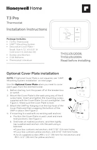 Honeywell TH3110U2008 Manual
 Honeywell TH4110D Manual
 Honeywell TH5000 Manual
 Honeywell TH5110D Manual
 Honeywell TH5220D Manual
 Honeywell TH6000 Manual