Page 6 - MONTAGE- UND GEBRAUCHSANWEISUNG; Elektrischer Anschluss
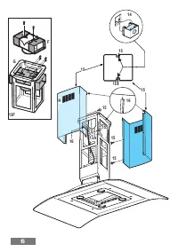
6 MONTAGE- UND GEBRAUCHSANWEISUNG D Bitte auch die Abbildungen auf den ersten Seiten mit denalphabetischen Bezugnahmen, die im Text wiedergegebensind, zu Hilfe nehmen. Die Instruktionen, die in diesemH a n d b u c h , g e g e b e n w e r d e n , b i t t e g a n z s t r e n ge i n h a l t e n . E s w...
Page 7 - W a r t u n g; W a r n u n g
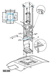
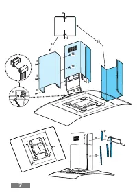
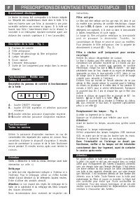
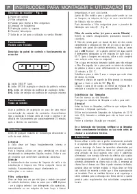
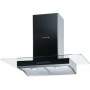
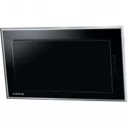
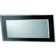
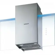
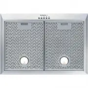
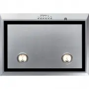
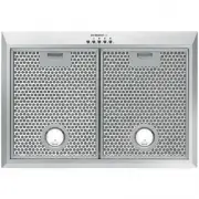
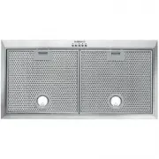
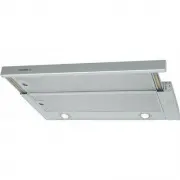
7 Beschreibung derDunstabzugshaube - Abb. 1 1 Bedienfeld2 Fettfilter3 Griff zum Aushaken des Fettfilters4 Halogenlampe5 D u n s t s c h i r m6 T e l e s k o p k a m i n7 Luftaustritt (nur bei Umluftbetrieb) Betrieb –Modell mit Tastenfeld A . S c h a l t e r O N / O F F B e l e u c h t u n g B . S c ...
Page 8 - Electrical connection; INSTRUCTION ON MOUNTING AND USE
8 Consult the designs in the front pages referenced in the textby alphabet letters. Closely follow the instructions setout in this manual. All responsibility, for any eventualinconveniences, damages or fires caused by not complyingwith the instructions in this manual, is declined. The cooker hood mu...
Page 9 - D e s c r i p t i o n o f c o n t r o l p a n e l a n d h o o d o p e r a t i o n; Maintenance
9 INSTRUCTION ON MOUNTING AND USE GB Description of the hood - Fig. 1 1 Control panel2 Grease filter3 Grease filter release handle4 Halogen lamp5 Vapour screen6 T e l e s c o p i c c h i m n e y7 Air outlet (used for filter version only) Operation –Model with button panel D e s c r i p t i o n o f c...
Page 10 - PRESCRIPTIONS DE MONTAGE ET MODE D’EMPLOI
1 0 PRESCRIPTIONS DE MONTAGE ET MODE D’EMPLOI F C o n s u l t e r l e s d e s s i n s d e l a p r e m i è r e p a g e a v e c l e sréférences alphabétiques que l’on retrouvera dans le texteexplicatif. Suivre strictement les instructions de cettenotice. Le constructeur décline toute responsabilité po...
Page 11 - Description de la hotte – Fig. 1
1 1 PRESCRIPTIONS DE MONTAGE ET MODE D’EMPLOI F Description de la hotte – Fig. 1 1 Panneau de contrôle 2 Filtre anti-graisse 3 Poignée de décrochage du filtre anti-graisse 4 L a m p e h a l o g è n e 5 É c r a n v a p e u r s 6 C h e m i n é e t é l e s c o p i q u e 7 Sortie de l’air (uniquement po...
Page 12 - MONTAGEVOORSCHRIFTEN EN GEBRUIKSAANWIIZING
1 2 Raadpleeg ook de tekeningen uit de eerste bladzijden metde alfabetische verwijzingen uit de toelichtende tekst.Zich strikt aan de aanwijzingen uit deze tekst houden.Iedere aansprakelijkheid voor eventuele schade of brandaan het apparaat veroorzaakt door het niet in acht nemen vande aanwijzingen ...
Page 13 - Elektrische aansluiting
1 3 Beschrijving vande wasemkap - afb. 1 1 B e d i e n i n g s p a n e e l 2 Vetfilter 3 Handgreep voor ontgrendeling van het vetfilter 4 H a l o g e e n l a m p 5 D a m p s c h e r m 6 T e l e s c o p i s c h e s c h o u w 7 Luchtuitgang (alleen voor gebruik als filterend apparaat) Werking – Model ...
Page 14 - ISTRUZIONI DI MONTAGGIO E D’USO; Collegamento elettrico
1 4 ISTRUZIONI DI MONTAGGIO E D’USO I Consultare anche i disegni nelle prime pagine con i riferimentialfabetici riportati nel testo esplicativo.A t t e n e r s i s t r e t t a m e n t e a l l e i s t r u z i o n i r i p o r t a t e i n q u e s t om a n u a l e . S i d e c l i n a o g n i r e s p o n...
Page 15 - B + C . S e l e z i o n e v e l o c i t à 2 ( i n c a s o d i m e d i a q u a n t i t à
1 5 ISTRUZIONI DI MONTAGGIO E D’USO I Descrizione della cappa - Fig. 1 1 Pannello di controllo 2 Filtro antigrasso 3 Maniglia di sgancio del filtro antigrasso 4 L a m p a d a a l o g e n a 5 S c h e r m o v a p o r i 6 C a m i n o t e l e s c o p i c o 7 Uscita aria (solo per utilizzo in versione fi...
Page 16 - MONTAJE Y MODO DE EMPLEO; Conexión eléctrica
1 6 MONTAJE Y MODO DE EMPLEO E Consulte tambien los dibujos de las primeras páginas conlas referencias alfabéticas del texto explicativo.Aténgase estrictamente a las instrucciones del presentemanual. Se declina cada responsabilidad por eventualesinconvenientes, daños o incendios provocados al aparat...
Page 17 - M a n t e n i m i e n t o; Advertencias
1 7 MONTAJE Y MODO DE EMPLEO E Descripción de la campana- Fig. 1 1 Cuadro de control2 Filtro antigrasa3 Manija de desenganche del filtro antigrasa4 Lámpara halógena5 Protección contra vapores6 C h i m e n e a t e l e s c ó p i c a7 Salida del aire (sólo para uso en versión filtrante) Funcionamiento ...
Page 18 - INSTRUÇÕES PARA MONTAGEM E UTILIZAÇÃO; Conexão elétrica
1 8 INSTRUÇÕES PARA MONTAGEM E UTILIZAÇÃO P Consultar também os desenhos nas primeiras páginas comas referências alfabéticas indicadas no texto explicativo.Ater-se especificamente às instruções indicadas nestemanual. Declina-se qualquer responsabilidade por eventuaisinconvenientes, danos ou incêndio...
Page 19 - Advertências
1 9 Descrição do exaustor – Fig. 1 1 Painel de controlo2 Filtro antigordura3 Puxador para libertar o filtro antigordura4 Lâmpada de halogéneos5 Protecção contra os vapores6 C h a m i n é t e l e s c ó p i c a7 Saída do ar (só para a utilização na versão filtrante) Funcionamento –Modelo com Teclado D...
Page 20 - MONTERINGS- OG BETJENINGSVEJLEDNING; D K; Elektrisk tilslutning
2 0 MONTERINGS- OG BETJENINGSVEJLEDNING D K S e v e n l i g s t o g s å t e g n i n g e r n e p å d e f ø r s t e s i d e r .Anvisningerne i denne vejledning skal følges. Vi kanikke gøres ansvarlige for skader sket som følge af mangelfuldeller forkert installation.E m s k æ r m e n s k a l m o n t e...
Page 21 - Funktion – alle modeller
2 1 MONTERINGS- OG BETJENINGSVEJLEDNING D K Beskrivelse af emhætten (fig. 1) 1 . B e t j e n i n g s p a n e l2 . Fedtfilter3 . Håndtag på fedtfilter4 . H a l o g e n l a m p e5 . S k æ r m6 . S k o r s t e n7 . Luftudgang (kun til recirkulation) Betjening –model med betjeningsknapper A . T æ n d / ...