Asrock B650 - Manuals
Asrock B650 Motherboard – User Manual in PDF format online.
Manuals:
User Manual Asrock B650


Summary
Contact Information If you need to contact ASRock or want to know more about ASRock, you’re welcome to visit ASRock’s website at http://www.asrock.com; or you may contact your dealer for further information. For technical questions, please submit a support request form at https://event.asrock.com/ts...
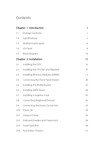
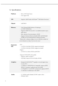
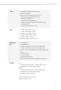
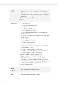
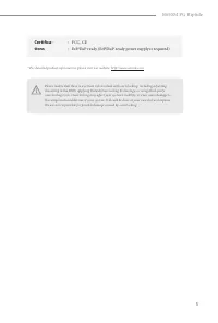
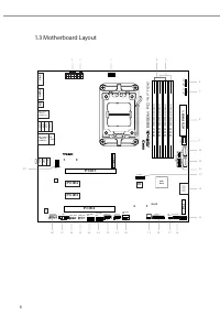
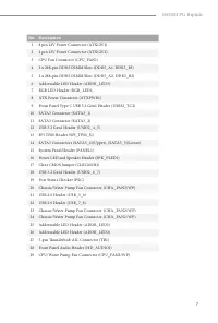
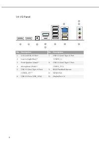
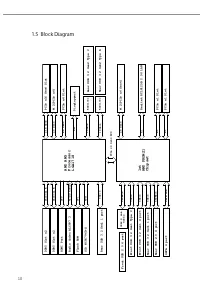
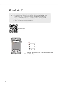
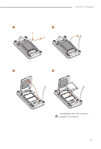
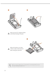
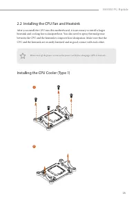
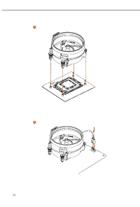
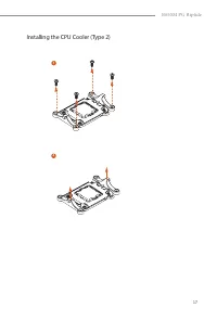
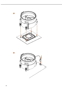
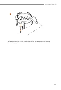
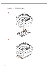
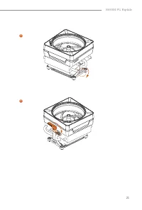
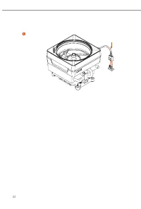
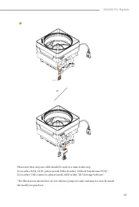
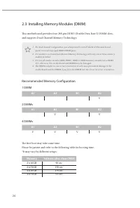
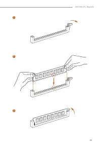
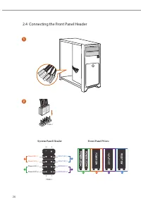
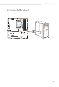
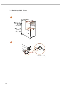
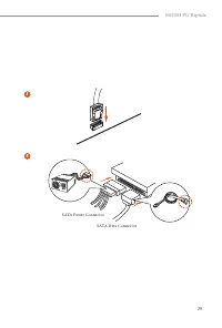
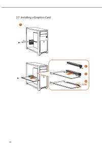
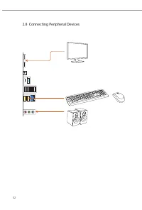
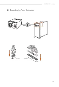
Contents Chapter 1 Introduction 1 1.1 Package Contents 1 1.2 Specifications 2 1.3 Motherboard Layout 6 1.4 I/O Panel 8 1.5 Block Diagram 10 Chapter 2 Installation 11 2.1 Installing the CPU 12 2.2 Installing the CPU Fan and Heatsink 15 2.3 Installing Memory Modules (DIMM) 24 2.4 Connecting the Front ...
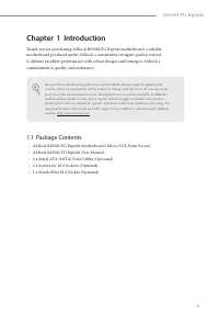
1 B650M PG Riptide Chapter 1 Introduction Thank you for purchasing ASRock B650M PG Riptide motherboard, a reliable motherboard produced under ASRock’s consistently stringent quality control. It delivers excellent performance with robust design conforming to ASRock’s commitment to quality and enduran...
Asrock Motherboards Manuals
-
 Asrock A320
User Manual
Asrock A320
User Manual
-
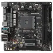 Asrock A320M-ITX
User Manual
Asrock A320M-ITX
User Manual
-
 Asrock A520M Pro4
User Manual
Asrock A520M Pro4
User Manual
-
 Asrock A520M-HVS
User Manual
Asrock A520M-HVS
User Manual
-
 Asrock A520M-ITX/ac
User Manual
Asrock A520M-ITX/ac
User Manual
-
 Asrock B365
User Manual
Asrock B365
User Manual
-
 Asrock B450
User Manual
Asrock B450
User Manual
-
 Asrock B450 Pro4
User Manual
Asrock B450 Pro4
User Manual
-
 Asrock B450M Pro4
User Manual
Asrock B450M Pro4
User Manual
-
 Asrock B450M-HDV R4.0
User Manual
Asrock B450M-HDV R4.0
User Manual
-
 Asrock B550
User Manual
Asrock B550
User Manual
-
 Asrock B550 PG
User Manual
Asrock B550 PG
User Manual
-
 Asrock B550 Pro4
User Manual
Asrock B550 Pro4
User Manual
-
 Asrock B550M
User Manual
Asrock B550M
User Manual
-
 Asrock B550M PG
User Manual
Asrock B550M PG
User Manual
-
 Asrock B550M Pro4
User Manual
Asrock B550M Pro4
User Manual
-
 Asrock B560
User Manual
Asrock B560
User Manual
-
 Asrock B560M
User Manual
Asrock B560M
User Manual
-
 Asrock B660
User Manual
Asrock B660
User Manual
-
 Asrock B660 Pro RS
User Manual
Asrock B660 Pro RS
User Manual