Telwin INVERPULSE 625 R A MIG TIG MMA - User Manual
Telwin INVERPULSE 625 R A MIG TIG MMA Welding Equipment – User Manual, read for free online in PDF format. We hope this helps you resolve any issues you may have. If you have further questions, please contact us through the contact form.
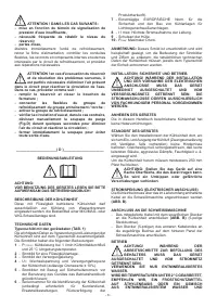
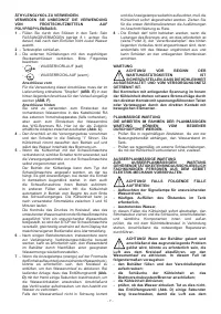
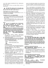
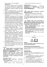
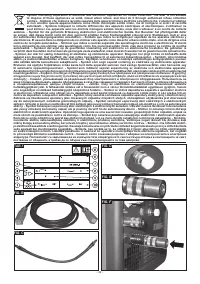
Table of Contents:
- Page 3 – su di una superficie piana di portata adeguata; d’acqua a fine riempimento.; specificato di seguito:; acqua insufficiente, viene comandato lo STOP della
- Page 7 – - Aufleuchten der Signallampe für unzureichenden
- Page 8 – superficie plana con una capacidad adecuada
- Page 10 – - Conectar as tubagens externas de resfriamento
- Page 12 – op de hierna gespecificeerde aspecten :; indien flex buizen van verbinding als verlenging
- Page 13 – Det viste specifikationsmærkat er et
- Page 14 – flexslanger til forbindelse med forlængelse, er det
- Page 15 – ud af stikkontakten, flexslangerne, overgangsstykkerne; - Fyld beholderen og skru lukkehætten fast; Yhdistä
- Page 16 – poistuu ja kierto palaa; : avkjølingseffekt ved et fløde på 1 liter/min av
- Page 17 – Identifiser installasjonsplassen for avkjølingsenheten slik; ADVARSEL! Plasser apparatet på en flatt; tankens KAPASITET er 8 liter. Vær nøye med å; følgende spesifikasjoner:; fleksible koplingsledninger, kan det bli nødvendig å
- Page 18 – sirkulasjonen aktiveres igjen; : kylningseffekt vid kylvätskeflöde på 1 l/min; I det exempel på skylt som visas här kan
- Page 19 – VOLYM = 8 l. Var uppmärksam på att inte fylla på för; - Koppla de externa kylslangarna till de avsedda; vattenslangar som finns i kabelbunten RA för extern; - Anslut kylarens flexslangar till drivenheten/
- Page 25 – exemplul de pe placa indicatoare prezentat
- Page 26 – CONECTAREA LA APARATUL DE SUDURĂ; ÎN CAZUL FOLOSIRII LA TEMPERATURI MAI MICI
- Page 27 – DANE TECHNICZNE; na tabliczce znamionowej podane jest; GO OD SIECI ZASILANIA.
- Page 29 – význam je následující:; Uvedený příklad štítku má pouze; Chladicí jednotka popsaná v tomto návodu není vybavena; KAPALINY NA BÁZI POLYPROPYLENU.; “. Chladicí jednotka bude uvedena
- Page 30 – JEDNOTKA VYPNUTÁ A ODPOJENÁ OD; UPOZORNĚNÍ! V PŘÍPADĚ VÝSKYTU; POPIS CHLADIACEJ JEDNOTKY; v zariadeniach pre zváranie MIG/MAG a TIG.; TECHNICKÉ ÚDAJE; a ich význam je nasledovný:
- Page 35 – pateiktas duomenų lentelės pavyzdys parodo; DĖMESIO! VISAS ĮRENGIMO IR ELEKTROS
- Page 36 – Bet kokie patikrinimai bloko viduje kai prijungta
- Page 37 – vidinius ir išorinius elementus, susijusius su aušinimo; DĖMESIO! Ištuštinus baką, bei išsprendus; - seerianumber jahutusseadme identifitseerimiseks; „papa“) keevitusseadme tagapaneelil olevasse
- Page 39 – attēlotajam plāksnītes piemēram ir ilustratīvs
- Page 44 – PISTOPOIHTIKO EGGUHSHS
- 1 -
____________________( GB )____________________
INSTRUCTION MANUAL
IMPORTANT NOTE:
BEFORE USING THE EQUIPMENT READ THE
INSTRUCTION MANUAL CAREFULLY!
DESCRIPTION OF THE COOLING UNIT
This liquid cooling unit must only be used for cooling MIG/
MAG and TIG water welding torches.
TECHNICAL DATA
Data plate (TAB. 1)
The main data relating to use and performance of the
cooling unit are summarised on the rating plate and have
the following meanings:
1
- P
1 l/min
: cooling power at a refrigerant flow rate of 1 l/
min and an ambient temperature of 25°C.
2
- symbol for system with liquid refrigerant.
3
- symbol for main power supply.
4
- U
1
: Alternating voltage and frequency of cooling unit
power supply (allowed limits ± 10% ).
5
- symbols referring to safety standards: before
using the apparatus read the instruction handbook
carefully!
6
- serial number for identifying the coolant unit
(essential when asking for servicing or spare parts,
or finding the origin of the product).
7
- EUROPEAN standard of reference for safety and
construction of cooling systems for arc welding.
8
- I
1 max
: maximum current absorbed by the line.
9
- Protection rating of enclosure.
10
- P
max
: maximum pressure.
NOTE:
The rating plate shown is an example to show the
meaning of the symbols and numbers; the exact values of
the technical properties of the cooling unit should be read
directly on the rating plate of the unit itself.
INSTALLATION, SAFETY AND OPERATIONS
WARNING!
ALL
THE
INSTALLATION
OPERATIONS AND ELECTRIC CONNECTIONS
SHOULD BE CARRIED OUT WITH THE
EQUIPMENT TURNED OFF AND DISCONNECTED
FROM THE POWER SUPPLY. EXPERT AND QUALIFIED
PERSONNEL MUST CARRY OUT THE ELECTRIC
CONNECTIONS.
LIFTING THE EQUIPMENT
The cooling unit described in this manual is not fitted with
lifting systems.
POSITIONING THE EQUIPMENT
The installation position for the cooling unit must be
chosen to ensure that the cooling air inlet and outlets are
not blocked in any way (forced fan circulation, if fitted); at
the same time, ensure that no conductive dust, corrosive
vapours, humidity, etc. could be sucked in.
A free space of at least 250 mm should be left around
the cooling unit.
WARNING! Position the equipment on a flat
surface adequate to support the weight, to
avoid it tipping over or making dangerous
movements.
POWER SUPPLY (ELECTRICAL CONNECTION)
The cooling unit must be connected to the welding
machine using the cable provided
(FIG.B)
.
CONNECTION TO THE WELDING MACHINE
-
Connect
the cable supplied
(FIG. B)
to the cooling unit,
using the dedicated connector (5-pin female).
- Connect the connector at the other end of the cable
(5-pin male) to the corresponding outlet on the back
panel of the welding machine.
OPERATIONS
ATTENTION! THE TANK CAN ONLY BE FILLED
AFTER HAVING SWITCHED OFF THE
APPARATUS AND DISCONNECTED IT FROM
THE MAINS.
ONLY USE DEMINERALISED WATER.
IF WORKING WITH TEMPERATURES OF BELOW 2 °C,
WE ADVISE USING ANTIFREEZE WITH AN ETHYLENE
BASE, OR A MIXTURE OF DEMINERALISED WATER
AND ETHYLENE GLYCOL.
DO NOT FOR ANY REASON USE POLYPROPYLENE
BASED ANTIFREEZE.
1 -
Fill the tank through the filler: tank CAPACITY = 8 l;
take care not to let the water overflow when the tank
is full.
2 -
Close the cap on the tank.
3 -
Connect the outer piping for the cooling to the
relative fittings, taking care of the following specific
instructions:
-
: WATER DELIVERY (Cold water)
-
: WATER RETURN (Hot water)
Front connections
In order to use these fittings it is necessary for the
”cap” provided
(FIG. E)
to be inserted in the rear
delivery connection
(FIG. F)
.
Rear connections
These are to be used for the fitting of water pipes
present in the RA cables bundle of the outer draft
(where present), but also for the fitting of the TIG
RA gun’s water piping, by interposing the adapter
available as an accessory
(Fig. C)
.
4 -
Make the connection to the power outlet and turn the
switch to position ”I”. The cooling unit will then start
operation, circulating the water in the torch.
5 -
If the cooling unit is connected to the welding
machine, the switch is not used because power
supply control is managed by the welding machine
Cod.953460
GB
............ pag. 01
I
................. pag. 02
F
............... pag. 04
D
............... pag. 06
E
...............
pag. 08
P
............... pag. 09
NL
............. pag. 11
DK
............ pag. 13
SF
............. pag. 15
N
............... pag. 16
S
...............
pag. 18
GR
............ pag. 20
RU
............ pag. 21
H
............... pag. 23
RO
............ pag. 25
PL
............. pag. 27
CZ
............. pag. 29
SK
............. pag. 30
SI
.............. pag. 32
HR/SCG
.... pag. 34
LT
............. pag. 35
EE
....... ...... pag. 37
LV
.............
pag. 38
BG
............ pag. 40
"Loading the manual" means you need to wait until the file loads and becomes available for online reading. Some manuals are very large, and the time they take to appear depends on your internet speed.
Summary
- 3 - INSTALLAZIONE, SICUREZZA E FUNZIONAMENTO ATTENZIONE! ESEGUIRE TUTTE LE OPERAZIONI DI INSTALLAZIONE ED ALLACCIAMENTI ELETTRICI CON L’APPARECCHIATURA RIGOROSAMENTE SPENTA E SCOLLEGATA DALLA RETE DI ALIMENTAZIONE. GLI ALLACCIAMENTI ELETTRICI DEVONO ESSERE ESEGUITI ESCLUSIVAMENTE DA PERSONALE ESPE...
- 7 - ÄTHYLENGLYKOL ZU VERWENDEN. VERMEIDEN SIE UNBEDINGT DIE VERWENDUNG VON FROSTSCHUTZMITTELN AUF POLYPROPYLENBASIS. 1 - Füllen Sie durch den Stützen in den Tank: Sein FASSUNGSVERMÖGEN beträgt 8 l; achten Sie darauf, daß nach dem Einfüllen nicht zuviel Wasser austritt. 2 - Tankstopfen schließen. 3...
- 8 - Kreislauf abgeführt wird und der Wasserumlauf in Schwung kommt; - sofort danach das Ventil schließen, um den Austritt von Wasser zu verhindern. _____________________( E )____________________ MANUAL DE INSTRUCCIONES ATENCIÓN: ¡ANTES DE UTILIZAR EL APARATO LEA ATENTAMENTE EL MANUAL DE INSTRUCCIO...