Page 2 - SKYLINK TECHNOLOGIES INC.; Total Protection Alarm System; Emergency Dialer; TABLE OF CONTENTS
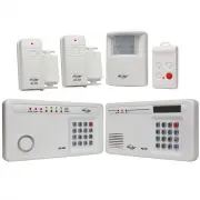
– 2 – SKYLINK TECHNOLOGIES INC. Total Protection Alarm System MODEL: SC-100 Emergency Dialer MODEL: AD-105 The SC-100 Total Protection Alarm System contains all the above items. Your Guide to this manual includes SC100 – The Alarm System and AD105 – The Emergency Dialer DIAL-ALERT TM The AD-105 Emer...
Page 3 - OVERVIEW; Congratulations; PACKAGE CONTENTS
– 5 – OVERVIEW Congratulations ! You have just purchased one of the most reliable and up-to-date wireless securitysystems on the market today. Skylink is the first company to incorporate the rollingcode technology in a home/business security system. This innovative technologyprovides increased secur...
Page 4 - PLANNING YOUR HOME SECURITY NEEDS; How to use the templates:; INSTALLATION
– – 6 PLANNING YOUR HOME SECURITY NEEDS You may choose to install a motion sensor to protect any valuables such asantiques or paintings. Point the motion sensor directly at the valuables and ifthey are disturbed in any way the alarm will be sounded. BEDROOM BEDROOM MASTER BEDROOM DOOR/WINDOW SENSOR ...
Page 5 - Transmitter Magnetic Switch Magnet Spacers; SENSOR SENSITIVITY
– – 8 1. P o s i t i o n t h e t r a n s m i t t e r b e - side the door/window frame onthe wall using either two sidedtape or screws. If you are usingscrews, first pry off the back platewith a small screwdriver andscrew the back plate into posi-tion using the template. Then clickthe transmitter on ...
Page 6 - WALK TEST; To set control panel to CHIME MODE; To test the Motion Sensor; TESTING YOUR SYSTEM
– 10 – INSTALLATION After mounting the sensor at the desired location, it isimportant to perform a walk test in order to determineif the sensor is detecting the things you want to detect. In order to control how far the sensor can “see”, this can be done by adjustingthe angle of the sensor. To reduc...
Page 7 - TO ARM THE SYSTEM USING THE KEYPAD ON THE CONTROL PANEL; Master Personal Identification Number; Arming sequences; Option 1: Away Sequence; STANDARD PROGRAMMING; LIGHTS
– 13 – Now that the system is installed and the sensors are communicating with theControl Panel, it is time to learn how to do basic programming of your securitysystem. More advanced features are explained further in the manual, (seeAdvanced Programming). You can arm and disarm the system by using e...
Page 8 - TO ARM SYSTEM USING THE KEYCHAIN TRANSMITTER; TO DISARM THE SYSTEM USING THE KEYPAD ON THE CONTROL PANEL
– 15 – TO ARM SYSTEM USING THE KEYCHAIN TRANSMITTER There are 2 different arm options to choose from: 1. Press button #1, and the Control Panel will beep once. The system will be armed in the Away Sequence. To be used to arm the systemwhen you are the last person leaving the premises . (see page 12 ...
Page 9 - PASSWORDS; MASTER PERSONAL IDENTIFICATION NUMBER (MPIN); Note
– 16 – – 17 – KEYCHAIN TRANSMITTER (4B-434) TO DISARM THE SYSTEM, OR DEACTIVATE THE SIREN USING THEKEYCHAIN TRANSMITTER When the system is armed: Press button #3.The red light on the transmitter flashes and the Control Panel beeps twice.The system is now disarmed. When the siren is sounding: Press b...
Page 10 - PROGRAM SENSORS TO DIFFERENT ZONES
– 18 – SECONDARY PERSONAL IDENTIFICATION NUMBER (SPIN) You may want to give someone limited access to the system, (baby sitter, cleaner,repairman etc.). For this purpose the SC-100 provides you with the option ofadding up to 3 separate SPIN. A SPIN can be any number of 3 digits or more. You can use ...
Page 11 - TO CLEAR A ZONE; TO DELETE A KEYCHAIN TRANSMITTER FROM ZONE 5:; ADVANCED PROGRAMMING
– 20 – ADVANCED PROGRAMMING To program sensors to send their signals to a different zone, you must first clearthem from communicating with their current zone. TO CLEAR A ZONE 1. Enter the current MPIN. 2. Press [ B ]. 3. Press the number key to identify current zone [ 1, 2, 3 or 4 ]. The zone light(...
Page 12 - TO CUSTOMIZE A SEQUENCE:; STANDARD ARMING SEQUENCES
– 23 – ADVANCED PROGRAMMING premises without activating the alarm. Zone 2 (the motion sensor), is off allowingmovement in the premises and zones 3 & 4 are instant. Option 2: Advanced Home 2 - use to secure the premises while staying in the building. Delays the alarm to allow someone to enter the...
Page 13 - SUMMARY OF ARMING SEQUENCES; CONTROL PANEL BATTERY; BATTERY MAINTENANCE
– 24 – Below is a table summarizing all the preprogrammed sequences. Sequence Zone 1 Zone 2 Zones 3 & 4 When sequence should be used FOR TESTING MPIN A # chime chime chime use for testing after installationand to test batteries, also use asa subtle chime when a remotesensor has been activated BA...
Page 15 - ADDITIONAL ACCESSORIES
Audio Alarm (AA-433) - Additional indoor/outdoor siren- Water resistant- 110 dB siren with flashing LED- Operates by AC adapter with 9V alkaline back up battery (included) Silent Alarm (SW-433) - Plug into any AC outlet, then plug light into Silent Alarm unit- Light flashes when sensor(s)/transmitte...
Page 16 - Emergency Dialer; CUSTOMER SERVICE
ADDITIONAL ACCESSORIES – 30 – Audio Sensor (AS-433) - Detects alarm sound from existing security system alarm; sends signal to Dial-Alert.- Eliminates need for monitoring service.- 9V alkaline battery included Temperature Sensor (TS-101A) - Monitors temperature of a specific area (i.e., greenhouse, ...
Page 18 - Pack of screws and anchors (for; Sensor Mode - Works with multiple sensors directly
– 34 – – 35 – All materials required for installation are included with this package 1 Dial-Alert (AD-105) 1 Telephone Line 1 antenna (installed) 1 AC adapter 1 9 volt alkaline battery 1 Pack of screws and anchors (for Dial-Alert ) One templateDouble sided tapeUser's instructionsWarranty CardQuick G...
Page 19 - Panic Devices; Sensors; Sensor; How to use the template:
– 37 – – 36 – OVERVIEW Dial Alert AD-105 must work with the specific sensors listed below. Ensure only thelisted sensors are used with the AD-105, otherwise, the communication between thesensors and the Dial Alert may not function properly. If you have a Skylink wirelessdevice or sensor that is not ...
Page 20 - The adapter cord must be inserted
– 38 – – 39 – INSTALLATION 3. Thread the AC adapter cord through the top hole in the back of the unit and plug it intothe AC connector on the circuit board asshown. The adapter cord must be inserted through the back of the unit before it isattached to the wall. 4. Insert the 9 volt battery and rotat...
Page 21 - LIGHTS AND SOUNDS; SELECTING THE OPERATION MODE; Sensor Mode
– 41 – – 40 – LIGHTS AND SOUNDS Below is an explanation of the lights and sounds of the Dial-Alert LIGHTS ACPWR light on dialer is being powered by AC adapter. ACPWR light off dialer is not receiving any AC power. LOBATT. light off backup battery is connected and working. LOBATT. light on backup bat...
Page 22 - RECORD A VOICE MESSAGE; Display now shows something like [L3 1 05] where the last 2 digits; PROGRAM A PHONE NUMBER
– – 42 43 – – STANDARD PROGRAMMING RECORD A VOICE MESSAGE You must record a message and program at least one phone number inorder for the Dial Alert to work. The voice recording procedure is different between the 2 operating modes,SC-001 Mode and Sensor Mode. To record a voice message under SC-001 M...
Page 23 - You may sometimes need to insert pause period in a phone num-; PROGRAM A SENSOR UNDER SENSOR OPERATING MODE; TESTING
– 45 – 44 – – Do not program the phone number to police or fire dept directly into your Dial-Alertunless you have checked with your local authorities. Please also inform all therecipients that their phone numbers have been programmed into your dialer, sothey know exactly what happens when they recei...
Page 24 - Sensor Mode; OPERATIONS
– – 46 47 – – OPERATIONS SC-001 Mode When the display shows “rEAdy”, that means the unit is in standby mode.It will dial when it receives a panic signal from the alarm panel, or its ownpanic button is pressed. It will dial the programmed phone numbers and playback the voicemessage. It is not necessa...
Page 25 - Changing Password; to set the calling time to 90 seconds.; Erase Programmed Panic Transmitters / Alarm Panels / Sensors; To erase all the wireless devices, follow the instructions below.; Dial Sequence
– 49 – – 48 – ADVANCED PROGRAMMING Changing Password Password is required for programming purposes. Factory default is 0000.To change the setting, follow the instructions below. 1. Enter the current password (factory default password is 0000), then press [PROG], display will show [P] meaning you are...
Page 26 - Pick up Pause Period; the pick up pause duration.; Entry / Exit Delay – For Sensor Mode; Enter any number from 1 to 5, which represents the entry / exit delay
– 50 – – 51 – 3. Enter [1] to disable universal dial tone meaning a proper dial tone must be presented before dialing, or [2] to enable universal dial tone, so theDial Alert will dial regardless of the dial tone. 4. If the new setting is accepted, it will emit 2 beeps. If you don’t hear 2 beeps, tha...
Page 27 - DIAL-ALERT QUICK GUIDE; CONNECT THE DIAL-ALERT WITH YOUR EXISTING ALARM SYSTEM; To replace the dialer backup battery:
– 53 – – 52 – ADVANCED PROGRAMMING DIAL-ALERT QUICK GUIDE [PIN]+[PROG]+[1] [PIN]+[PROG]+[2] [PIN]+[PROG]+[3] [PIN]+[PROG]+[4] [PIN]+[PROG]+[5] [PIN]+[PROG]+[6] [PIN]+[PROG]+[7] [PIN]+[PROG]+[8] [PIN]+[PROG]+[9] Operating Mode Change Password Voice Message Recording Phone Number Program Sensors / Tra...