Ridgid R4331 - User Manual

Ridgid R4331 Electric Planer – User Manual, read for free online in PDF format. We hope this helps you resolve any issues you may have. If you have further questions, please contact us through the contact form.


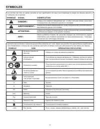
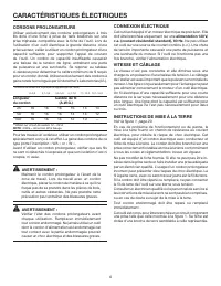
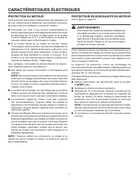
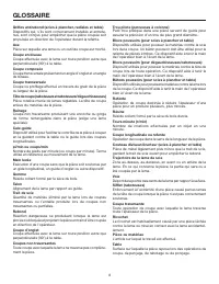
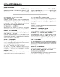
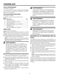
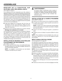
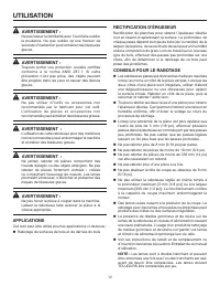
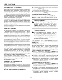
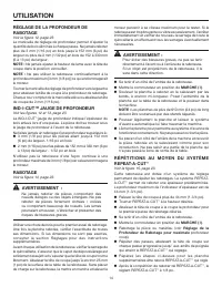
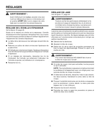
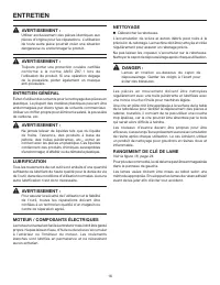
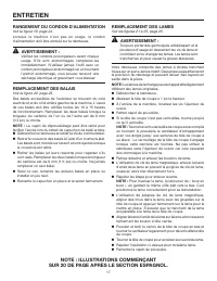
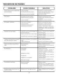
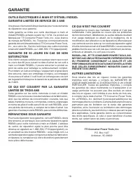


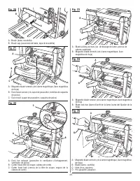
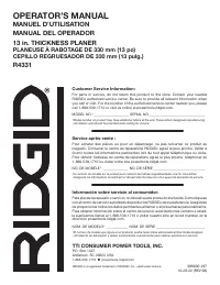
Table of Contents:
- Page 2 – GENERAL SAFETY RULES; READ ALL INSTRUCTIONS
- Page 4 – SPECIFIC SAFETY RULES
- Page 5 – SYMBOLS
- Page 6 – ELECTRICAL; ELECTRICAL CONNECTION; SPEED AND WIRING
- Page 7 – MOTOR SAFETY PROTECTION; MOTOR OVERLOAD PROTECTOR
- Page 8 – GLOSSARY OF TERMS
- Page 9 – FEATURES
- Page 10 – UNPACKING; ASSEMBLY; MOUNTING THE PLANER TO WORKBENCH
- Page 11 – CLAMPING PLANER TO WORKBENCH; INSTALLING THE DUST GUIDE
- Page 12 – OPERATION; APPLICATIONS
- Page 13 – AVOIDING SNIPE; CARRIAGE LOCK
- Page 14 – ADJUSTING PLANING DEPTH
- Page 15 – THICKNESS SCALE ADJUSTMENT; ADJUSTMENTS; BLADE ADJUSTMENT
- Page 16 – MAINTENANCE; GENERAL MAINTENANCE
- Page 17 – CORD STORAGE; NOTE: ILLUSTRATIONS START ON PAGE 20 AFTER
- Page 18 – TROUBLESHOOTING; PROBLEM
- Page 19 – WARRANTY
- Page 20 – RÈGLES DE SÉCURITÉ GÉNÉRALES; LIRE TOUTES LES INSTRUCTIONS
- Page 22 – RÈGLES DE SÉCURITÉ PARTICULIÈRES
- Page 23 – SYMBOLES
- Page 24 – CARACTÉRISTIQUES ÉLECTRIQUES; CORDONS PROLONGATEURS; CONNEXION ÉLECTRIQUE; VITESSE ET CÂBLAGE
- Page 25 – PROTECTION DU MOTEUR; PROTECTEUR DE SURCHAUFFE DU MOTEUR
- Page 26 – GLOSSAIRE
- Page 27 – CARACTÉRISTIQUES
- Page 28 – DÉBALLAGE; ASSEMBLAGE
- Page 29 – M O N T A G E D E L A R A B O T E U S E S U R; INSTALLATION DE LA GUIDE À POUSSIÈRE
- Page 30 – UTILISATION; RECTIFICATION D’ÉPAISSEUR
- Page 32 – RABOTAGE
- Page 33 – RÉGLAGE DE L’ÉCHELLE D’ÉPAISSEUR; RÉGLAGES; RÉGLAGE DE LAME
- Page 34 – RANGEMENT DE CLÉ DE LAME; ENTRETIEN
- Page 35 – RANGEMENT DU CORDON D’ALIMENTATION; NOTE : ILLUSTRATIONS COMMENÇANT
- Page 36 – RECHERCHE DE PANNES; PROBLÈME
- Page 37 – GARANTIE; RÉPARATIONS SOUS GARANTIE; AUTRES LIMITATIONS
- Page 38 – REGLAS DE SEGURIDAD GENERALES; LEA TODAS LAS INSTRUCCIONES
- Page 39 – REGLAS DE SEGURIDAD ESPECÍFICAS
- Page 41 – SÍMBOLOS; SÍMBOLO
- Page 42 – ASPECTOS ELÉCTRICOS; CORDONES DE EXTENSIÓN; CONEXIÓN ELÉCTRICA; VELOCIDAD Y CABLEADO; INSTRUCCIONES DE CONEXIÓN A TIERRA
- Page 43 – PROTECCIÓN DE SEGURIDAD DEL MOTOR; PROTECTOR CO
- Page 44 – GLOSARIO DE TÉRMINOS
- Page 45 – CARACTERISTICAS; CALIBRE DE PROFUNDIDAD; BOTÓN DE REAJUSTE
- Page 46 – HERRAMIENTAS NECESARIAS; LISTA DE PIEZAS SUELTAS; DESEMPAQUETADO; ARMADO
- Page 47 – INSTALACION DE GUÍA DEL POLVO
- Page 48 – USOS; CEPILLADO DE REGRUESAMIENTO; FUNCIONAMIENTO
- Page 49 – USO DE SEGURO DE LA CABEZA DEL CARRO
- Page 50 – R E C E P I L L A D O / U S O D E L A C U B I E R T A
- Page 51 – AJUSTE DE LA ESCALA DE GROSOR; AJUSTES; AJUSTE DE LAS CUCHILLAS
- Page 52 – LUGAR DE GUARDAR LA LLAVE DE LA HOJA; MANTENIMIENTO
- Page 53 – ALMACENAMIENTO DEL CORDÓN
- Page 54 – SOLUCIÓN DE PROBLEMAS; PROBLEMA
- Page 55 – GARANTÍA; LO QUE ESTÁ CUBIERTO EN LA GARANTÍA DE; LIMITACIONES ADICIONALES
- Page 62 – OPERATOR’S MANUAL; Customer Service Information:; Información sobre servicio al consumidor:
OPERATOR’S MANUAL
MANUEL D’UTILISATION
MANUAL DEL OPERADOR
13 in. THICKNESS PLANER
PLANEUSE À RABOTAGE DE 330 mm (13 po)
CEPILLO REGRUESADOR DE 330 mm (13 pulg.)
R4331
To register your RIDGID
product, please visit:
http://register.RIDGID.com
Pour enregistrer votre
produit de RIDGID,
s’il vous plaît la visite :
http://register.RIDGID.com
Para registrar su producto
de RIDGID, por favor visita:
http://register.RIDGID.com
WARNING:
To reduce the risk of injury, the
user must read and understand the
operator’s manual before using this
product.
ADVERTENCIA:
Para reducir el riesgo de lesiones, el
usuario debe leer y comprender el
manual del operador antes de usar
este producto.
AVERTISSEMENT :
Pour réduire les risques de blessures,
l’utilisateur doit lire et veiller à bien
comprendre le manuel d’utilisation
avant d’employer ce produit.
TABLE OF CONTENTS
****************
General Safety Rules ....................... 2-3
Specific Safety Rules ...................... 3-4
Symbols ...............................................5
Electrical .......................................... 6-7
Glossary of Terms ...............................8
Features ...............................................9
Assembly ..................................... 10-11
Operation ..................................... 12-14
Adjustments ......................................15
Maintenance ................................ 16-17
Troubleshooting ................................18
Warranty ............................................19
Parts Ordering / Service ...... Back Page
TABLE DES MATIÈRES
****************
Règles de sécurité générales .......... 2-3
Règles de sécurité particulières ...... 3-4
Symboles .............................................5
Caractéristiques électriques ............ 6-7
Glossaire .............................................8
Caractéristiques ..................................9
Assemblage ................................. 10-11
Utilisation ..................................... 12-14
Réglages ............................................15
Entretien ...................................... 16-17
Dépannage ........................................18
Garantie .............................................19
Commande de pièces /
réparation .......................... Page arrière
ÍNDICE DE CONTENIDO
****************
Reglas de seguridad generales ....... 2-3
Reglas de seguridad específicas .... 3-4
Símbolos .............................................5
Aspectos eléctricos ......................... 6-7
Glosario de términos ...........................8
Características ....................................9
Armado ........................................ 10-11
Funcionamiento ........................... 12-14
Ajustes ...............................................15
Mantenimiento ............................. 16-17
Corrección de problemas ..................18
Garantía .............................................19
Pedidos de piezas /
servicio ........................... Pág. posterior
SAVE THIS MANUAL FOR
FUTURE REFERENCE
GUARDE ESTE MANUAL
PARA FUTURAS CONSULTAS
CONSERVER CE MANUEL
POUR FUTURE RÉFÉRENCE
"Loading the manual" means you need to wait until the file loads and becomes available for online reading. Some manuals are very large, and the time they take to appear depends on your internet speed.
Was this manual helpful?
About this manual
- Brand
- Ridgid
- Model
- R4331
- Document type
- User Manual
- Category
- Electric Planer
- Language(s)
- English, Spanish, French
- Pages
- 62
- File size
- 2.6 MB
- Format
Summary
2 GENERAL SAFETY RULES WARNING: Read and understand all instructions. Failure to follow all instructions listed below, may result in electric shock, fire and/or serious personal injury. READ ALL INSTRUCTIONS KNOW YOUR POWER TOOL. Read the operator’s manual carefully. Learn the tool’s applications ...
4 SPECIFIC SAFETY RULES NEVER PUT YOUR FINGERS into the dust hood or under the cutter guard. ALLOW THE CUTTER HEAD to reach full speed before using the planer. REPLACEMENT PARTS. All repairs, whether electrical or mechanical, should be made at your nearest authorized service center. DO NOT a...
5 SYMBOLS The following signal words and meanings are intended to explain the levels of risk associated with this product. SYMBOL SIGNAL MEANING DANGER: Indicates a hazardous situation, which, if not avoided, will result in death or serious injury. WARNING: Indicates a hazardous situation, which, if...
Ask a question
Related manuals
More Ridgid Electric Planers models
Other Ridgid appliances
 Ridgid 122XL Manual
 Ridgid 258 Manual
- Ridgid 258XL Manual
 Ridgid 300 Manual
 Ridgid 600 Manual
 Ridgid 690 Manual
 Ridgid 700 Manual
 Ridgid 902 Manual
 Ridgid 1210 Manual
 Ridgid 1233 Manual
 Ridgid 2032-OS Manual
- Ridgid 2048-OS Manual
- Ridgid 3068-OS Manual
 Ridgid AC9940 Manual
 Ridgid AC9944 Manual
 Ridgid AC99401 Manual
 Ridgid AC840060SB1-R86344B User Manual
 Ridgid BS1400 Manual