Maytag MDE20MNBYW - User Manual

Maytag MDE20MNBYW Dryer – User Manual, read for free online in PDF format. We hope this helps you resolve any issues you may have. If you have further questions, please contact us through the contact form.

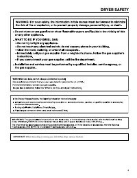


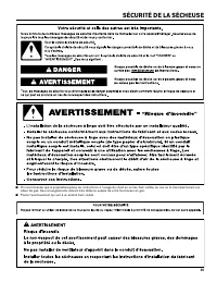
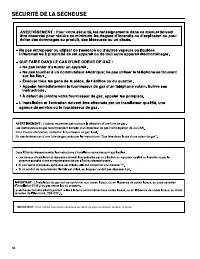
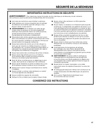

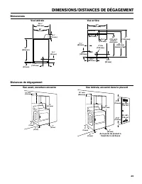
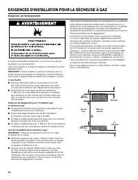
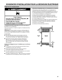
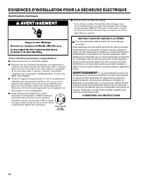
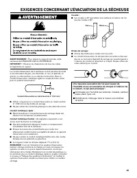
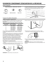
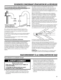
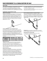
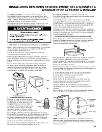
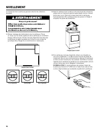
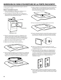
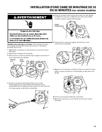
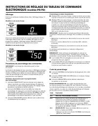

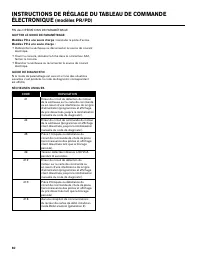


Table of Contents:
- Page 2 – DRYER SAFETY
- Page 4 – IMPORTANT SAFETY INSTRUCTIONS; including the following:; SAVE THESE INSTRUCTIONS
- Page 6 – DIMENSIONS/CLEARANCES; Side View; Dimensions; Front View, Recessed Opening
- Page 7 – Location Requirements; GAS DRYER INSTALLATION REQUIREMENTS
- Page 8 – Gas Dryer Grounding; Electrical Requirements
- Page 9 – Gas Supply
- Page 10 – ELECTRIC DRYER INSTALLATION REQUIREMENTS
- Page 11 – Electric Dryer Grounding
- Page 12 – Direct Wire; Electrical Requirements – Canada only; GROUNDING INSTRUCTIONS
- Page 13 – DRYER VENTING REQUIREMENTS
- Page 14 – Vent Hoods; Vent System Length
- Page 15 – Make Gas Connection; GAS SUPPLY CONNECTION; If an Exhaust Hood Cannot be Used
- Page 16 – Type of Gas; Gas Supply Line
- Page 17 – INSTALLING LEVELING LEGS, COIN SLIDE, AND COIN BOX
- Page 18 – ELECTRIC DRYER ELECTRICAL CONNECTIONS; Remove Terminal Block Cover; Power Supply Cord Connection; Power Cord; Connection Options
- Page 19 – Connecting 4-Wire Connection: Power Supply Cord; A 4-wire connection is required for mobile
- Page 20 – Direct Wire Connection; Remove hold-down screw and terminal block cover.
- Page 21 – Connecting 4-Wire Connection: Direct Wire
- Page 22 – Connecting 3-Wire Connection: Direct Wire
- Page 23 – LEVELING
- Page 24 – COMPLETE INSTALLATION
- Page 25 – Remove the Door Assembly
- Page 26 – CHANGING TO A 30- OR 60-MINUTE TIMING CAM; WARNING
- Page 28 – ELECTRONIC CONTROL SETUP INSTRUCTIONS; General User Information
- Page 29 – Control Set-up Procedures
- Page 34 – NOTES
- Page 35 – SÉCURITÉ DE LA SÉCHEUSE
- Page 37 – IMPORTANTES INSTRUCTIONS DE SÉCURITÉ
- Page 38 – OUTILS ET PIÈCES; Outillage nécessaire :
- Page 39 – DIMENSIONS/DISTANCES DE DÉGAGEMENT
- Page 40 – Exigences de l’emplacement; EXIGENCES D’INSTALLATION POUR LA SÉCHEUSE À GAZ
- Page 41 – Mise à la terre de la sécheuse à gaz; Spécifications électriques
- Page 42 – Alimentation en gaz
- Page 43 – EXIGENCES D’INSTALLATION POUR LA SÉCHEUSE ÉLECTRIQUE
- Page 44 – INSTRUCTIONS DE LIAISON À LA TERRE
- Page 45 – EXIGENCES CONCERNANT L’ÉVACUATION DE LA SÉCHEUSE
- Page 46 – Hottes d’extraction; Longueur du système d’évacuation
- Page 47 – Raccordement à la canalisation de gaz; RACCORDEMENT À LA CANALISATION DE GAZ; Si on ne peut pas utiliser de clapet d’évacuation
- Page 48 – Type de gaz; Canalisation d’alimentation en gaz
- Page 49 – INSTALLATION DES PIEDS DE NIVELLEMENT, DE LA GLISSIÈRE À
- Page 50 – NIVELLEMENT
- Page 51 – ACHEVER L’INSTALLATION
- Page 52 – INVERSION DU SENS D’OUVERTURE DE LA PORTE (FACULTATIF); Retirer l’assemblée de porte
- Page 55 – Informations générales d’utilisation
- Page 56 – Code de paramétrage; Affichage
www.maytagcommerciallaundry.com
W10868655A
W10868673A – SP
TABLE OF CONTENTS
DRYER SAFETY .................................................................................................. 2
TOOLS & PARTS ............................................................................................... 5
DIMENSIONS/CLEARANCES ................................................................. 6
GAS DRYER INSTALLATION REQUIREMENTS .............................. 7
ELECTRIC DRYER INSTALLATION REQUIREMENTS .............. 10
DRYER VENTING REQUIREMENTS ................................................. 13
GAS SUPPLY CONNECTION ................................................................. 15
INSTALLING LEVELING LEGS, COIN SLIDE, AND
COIN BOX ......................................................................................................... 17
ELECTRIC DRYER ELECTRICAL CONNECTIONS ..................... 18
LEVELING ......................................................................................................... 23
COMPLETE INSTALLATION ..................................................................... 24
REVERSING DRYER DOOR SWING ................................................... 25
CHANGING TO A 30- OR 60-MINUTE TIMING CAM ................. 26
MAINTENANCE INSTRUCTIONS ......................................................... 27
IF YOU NEED ASSISTANCE ................................................................... 27
ELECTRONIC CONTROL SETUP INSTRUCTIONS ................... 28
WARRANTY ........................................................................................................ 33
TABLE DES MATIÈRES
SÉCURITÉ DE LA SÉCHEUSE ............................................................ 35
OUTILS ET PIÈCES .................................................................................. 38
DIMENSIONS/DISTANCES DE DÉGAGEMENT ...................... 39
EXIGENCES D’INSTALLATION POUR LA
SÉCHEUSE À GAZ ..................................................................................... 40
EXIGENCES D’INSTALLATION POUR
LA SÉCHEUSE ÉLECTRIQUE ........................................................... 43
EXIGENCES CONCERNANT L’ÉVACUATION
DE LA SÉCHEUSE .................................................................................... 45
RACCORDEMENT À LA CANALISATION DE GAZ .................... 47
INSTALLATION DES PIEDS DE NIVELLEMENT,
DE LA GLISSIÈRE À MONNAIE ET DE LA CAISSE
À MONNAIE .................................................................................................. 49
NIVELLEMENT ..............................................................................................50
ACHEVER L’INSTALLATION ....................................................................51
INVERSION DU SENS D’OUVERTURE DE
LA PORTE .........................................................................................................52
INSTALLATION D’UNE CAME DE MINUTAGE
DE 30 OU 60 MINUTES ...........................................................................53
INSTRUCTIONS D’ENTRETIEN ...........................................................54
SI VOUS AVEZ BESOIN D’ASSISTANCE ........................................54
INSTRUCTIONS DE RÉGLAGE DU TABLEAU
DE COMMANDE ÉLECTRONIQUE ................................................... 55
GARANTIE .........................................................................................................61
INSTALLATION INSTRUCTIONS
C
ommerCial
D
ryer
G
as
or
e
leCtriC
INSTRUCTIONS D’INSTALLATION
s
éCheuse
à
usaGe
CommerCial
à
Gaz
ou
éleCtrique
"Loading the manual" means you need to wait until the file loads and becomes available for online reading. Some manuals are very large, and the time they take to appear depends on your internet speed.
Summary
2 DRYER SAFETY ■ It is recommended that the owner post, in a prominent location, instructions for the customer’s use in the event the customer smells gas. This information should be obtained from your gas supplier. ■ Post the following warning in a prominent location.
4 DRYER SAFETY ■ Clean dryer lint screen before or after each load. ■ Do not use this dryer without the lint screen in place. ■ Do not repair or replace any part of the dryer or attempt any servicing unless specifically recommended in this Installation Instructions or in published user-repair instru...
6 DIMENSIONS/CLEARANCES Side View Back View Dimensions Clearances 29 1 / 4 " ( 743 mm ) 35" (889 mm) 8 1 / 4 " ( 210 mm ) 1" ( 25 mm ) 26" (660 mm) 3 1 / 4 " ( 83 mm ) 7 1 / 2 " ( 191 mm ) 0" (0 mm) 0" (0 mm) 15" (381 mm) 14" max (356 mm) 0" (0 mm) 1 1...