Page 2 - DRYER SAFETY
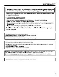
2 DRYER SAFETY ■ It is recommended that the owner post, in a prominent location, instructions for the customer’s use in the event the customer smells gas. This information should be obtained from your gas supplier. ■ Post the following warning in a prominent location.
Page 4 - IMPORTANT SAFETY INSTRUCTIONS; including the following:; SAVE THESE INSTRUCTIONS
4 DRYER SAFETY ■ Clean dryer lint screen before or after each load. ■ Do not use this dryer without the lint screen in place. ■ Do not repair or replace any part of the dryer or attempt any servicing unless specifically recommended in this Installation Instructions or in published user-repair instru...
Page 6 - DIMENSIONS/CLEARANCES; Side View; Dimensions; Front View, Recessed Opening
6 DIMENSIONS/CLEARANCES Side View Back View Dimensions Clearances 29 1 / 4 " ( 743 mm ) 35" (889 mm) 8 1 / 4 " ( 210 mm ) 1" ( 25 mm ) 26" (660 mm) 3 1 / 4 " ( 83 mm ) 7 1 / 2 " ( 191 mm ) 0" (0 mm) 0" (0 mm) 15" (381 mm) 14" max (356 mm) 0" (0 mm) 1 1...
Page 7 - Location Requirements; GAS DRYER INSTALLATION REQUIREMENTS
7 Your dryer can be installed in a basement, laundry room, or recessed area.Companion appliance location requirements should also be considered. IMPORTANT: Do not install or store the dryer where it will be exposed to the weather. Proper installation is your responsibility. You will need: ■ A ground...
Page 8 - Gas Dryer Grounding; Electrical Requirements
8 Gas Dryer Grounding IMPORTANT: The dryer must be electrically grounded in accordance with local codes and ordinances or, in the absence of local codes, with the National Electrical Code, ANSI/NFPA 70, latest edition, or Canadian Electrical Code, CSA C22.1. If codes permit and a separate ground wir...
Page 9 - Gas Supply
9 IMPORTANT: Observe all governing codes and ordinances. This installation must conform with all local codes and ordinances. In the absence of local codes, installation must conform with American National Standard, National Fuel Gas Code ANSI Z223.1/NFPA 54 or CAN/CSA B149.A copy of the above code s...
Page 10 - ELECTRIC DRYER INSTALLATION REQUIREMENTS
10 Your dryer can be installed in a basement, laundry room, or recessed area.Companion appliance location requirements should also be considered. IMPORTANT: Do not install or store the dryer where it will be exposed to the weather. Proper installation is your responsibility. You will need: ■ A groun...
Page 11 - Electric Dryer Grounding
11 Electrical Requirements – U.S.A. only (cont.) Electrical Connection To properly install your dryer, you must determine the type of electrical connection you will be using and follow the instructions provided for it here. ■ This dryer is manufactured ready to install with a 3-wire electrical suppl...
Page 12 - Direct Wire; Electrical Requirements – Canada only; GROUNDING INSTRUCTIONS
12 Direct Wire If connecting by direct wire: Power supply cable must match power supply (4-wire or 3-wire) and be: ■ Flexible armored cable or nonmetallic sheathed copper cable (with ground wire), covered with flexible metallic conduit. All current-carrying wires must be insulated. ■ 10-gauge solid ...
Page 13 - DRYER VENTING REQUIREMENTS
13 DRYER VENTING REQUIREMENTS WARNING: To reduce the risk of fire, this dryer MUST BE EXHAUSTED OUTDOORS. IMPORTANT: Observe all governing codes and ordinances. Dryer exhaust must not be connected into any gas vent, chimney, wall, ceiling, attic, crawlspace, or a concealed space of a building. Only ...
Page 14 - Vent Hoods; Vent System Length
14 4" (102 mm) Diameter Exhaust Hoods Box Hood Louvered Hood Angled Hood Vent Hoods DRYER VENTING REQUIREMENTS Exhaust hood must be at least 12" (305 mm) from the ground or any object that may be in the path of the exhaust (such as flowers, rocks, bushes, or snow). Maximum Vent Length/Vent C...
Page 15 - Make Gas Connection; GAS SUPPLY CONNECTION; If an Exhaust Hood Cannot be Used
15 DRYER VENTING REQUIREMENTS 1. Connect gas supply to dryer. Use a pipe thread compound approved for the type of gas supplied. If flexible metal tubing is used, be certain there are no kinks.If necessary for service, open the toe panel. Use a putty knife to press on the toe panel lock located at th...
Page 16 - Type of Gas; Gas Supply Line
16 This dryer is equipped for use with natural gas. It is design-certified by CSA International for LP (propane and butane) gases with appropriate conversion. No attempt shall be made to convert dryer from gas specified on serial/rating plate for use with a different gas without consulting the servi...
Page 17 - INSTALLING LEVELING LEGS, COIN SLIDE, AND COIN BOX
17 INSTALLING LEVELING LEGS, COIN SLIDE, AND COIN BOX On some models: The console houses the electronic control board. The board is factory set for a dry time of 5 minutes. Consult the tech sheet found inside the dryer toe panel to reset dry time and for other options.The card reading mechanism is n...
Page 18 - ELECTRIC DRYER ELECTRICAL CONNECTIONS; Remove Terminal Block Cover; Power Supply Cord Connection; Power Cord; Connection Options
18 ELECTRIC DRYER ELECTRICAL CONNECTIONS (FOR U.S.A. ONLY) 2. Insert power cord into strain relief. Remove Terminal Block Cover Power Supply Cord Connection Remove hold-down screw and terminal block cover. Put power supply cord through the strain relief. Be sure that the wire insulation on the power...
Page 19 - Connecting 4-Wire Connection: Power Supply Cord; A 4-wire connection is required for mobile
19 ELECTRIC DRYER ELECTRICAL CONNECTIONS (FOR U.S.A. ONLY) Connecting 4-Wire Connection: Power Supply Cord Connecting 3-Wire Connection: Power Supply Cord Standard Power Supply Cord Connectors Flanged Spade Connector Ring Connector Connecting Neutral Ground and Neutral Wires1. Remove center terminal...
Page 20 - Direct Wire Connection; Remove hold-down screw and terminal block cover.
20 ELECTRIC DRYER ELECTRICAL CONNECTIONS (FOR U.S.A. ONLY) F F Direct Wire Connection Remove Terminal Block Cover Remove hold-down screw and terminal block cover. Direct Wire Strain Relief1. Insert strain relief. Unscrew the removable conduit connector (A) and any screws from a ¾" (19 mm) UL lis...
Page 21 - Connecting 4-Wire Connection: Direct Wire
21 ELECTRIC DRYER ELECTRICAL CONNECTIONS (FOR U.S.A. ONLY) Connecting 4-Wire Connection: Direct Wire 2. Connect neutral ground wire (B) and place hooked end (hook facing right) of neutral wire (white or center wire) (D) of direct wire cable under center terminal block screw (A). Squeeze hooked ends ...
Page 22 - Connecting 3-Wire Connection: Direct Wire
22 ELECTRIC DRYER ELECTRICAL CONNECTIONS (FOR U.S.A. ONLY) Connecting 3-Wire Connection: Optional 2. Place hooked end of neutral wire (white or center wire) (D) of direct wire cable under center terminal block screw (A), hook facing right. Squeeze hooked end together and tighten screw. 3. Connect re...
Page 23 - LEVELING
23 1. Remove cardboard from beneath dryer. Place a level on top edges of dryer, checking each side and front. If not level, tip dryer and adjust legs up or down as shown in Step 3, repeating as necessary. LEVELING Leveling your dryer properly reduces excess noise and vibration. Not Level LEVEL Not L...
Page 24 - COMPLETE INSTALLATION
24 1. Check the electrical requirements. Be sure that you have the correct electrical supply and the recommended grounding method. See “Electrical Requirements.” 2. Check that all parts are now installed. If there is an extra part, go back through the steps. 3. Check that you have all of your tools....
Page 25 - Remove the Door Assembly
25 REVERSING DRYER DOOR SWING (OPTIONAL) 9. Attach door hinges to dryer door so that larger hole is at the bottom of the hinge and the hinge pin is toward the door front. 10. Remove the 4 screws that attach 2 plugs on the left side. Attach plugs to right side using the same 4 screws. 11. Insert scre...
Page 26 - CHANGING TO A 30- OR 60-MINUTE TIMING CAM; WARNING
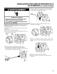
26 Coin-slide models: You can install the 30-minute or 60-minute timing cam (shipped with dryer) as follows: 1. Unplug dryer or disconnect power. 2. Unlock meter case. 3. Turn the timing cam by hand until the V-shaped notch lines up below the ratchet tooth. 4. Insert a narrow, flat-blade screwdriver...
Page 28 - ELECTRONIC CONTROL SETUP INSTRUCTIONS; General User Information
28 ELECTRONIC CONTROL SETUP INSTRUCTIONS (PR/PD models) General User Information BLANK DISPLAY – This condition indicates the dryer is inoperative. Enter set-up mode to view diagnostic code. “0 MINUTES” SHOWING IN DISPLAY – This indicates the cycle is complete and the dryer cannot be operated. Coins...
Page 29 - Control Set-up Procedures
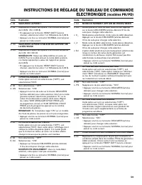
29 ELECTRONIC CONTROL SETUP INSTRUCTIONS (PR/PD models) The set-up code is indicated by the one or two left-hand characters. The set-up code value is indicated by the two or three right-hand characters. Code Explanation 606 REGULAR CYCLE PRICE 606 Represents the number of quarters (coin 1) needed to...
Page 34 - NOTES
Page 35 - SÉCURITÉ DE LA SÉCHEUSE
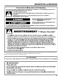
35 SÉCURITÉ DE LA SÉCHEUSE ■ On recommande que le propriétaire place les instructions à l’usage du client en un lieu bien visible, au cas où le client percevrait une odeur de gaz. Ces renseignements doivent être obtenus auprès de votre fournisseur en gaz. ■ Placer l’avertissement qui suit à un endro...
Page 37 - IMPORTANTES INSTRUCTIONS DE SÉCURITÉ
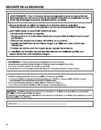
37 SÉCURITÉ DE LA SÉCHEUSE ■ Ne pas utiliser cette sécheuse si le filtre à peluches n’est pas installé. ■ Ne pas réparer ou remplacer un composant quelconque de la sécheuse, ni entreprendre une opération de service, si ce n’est spécifiquement recommandé dans ce manuel ou dans un manuel d’instruction...
Page 38 - OUTILS ET PIÈCES; Outillage nécessaire :
38 OUTILS ET PIÈCES †® TORX et T25 sont les marques déposée de Acument Intellectual Properties, LLC. Pièces fournies : Patins (4) Pieds de la sécheuse (4) Plaque indicatrice (modèles PR seulement) Coin Boulon de 5/16" – Came de minutage de 60 minutes Came de minutage de 30 minutes (modèles PD se...
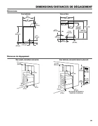
Page 39 - DIMENSIONS/DISTANCES DE DÉGAGEMENT
39 Vue latérale Vue arrière Dimensions Distances de dégagement Vue avant, ouverture encastre Vue latérale, encastré dans le placard 0" (0 mm) 0" (0 mm) 15" (381 mm) 14" max (356 mm) 0" (0 mm) 29 1 / 4 " ( 743 mm ) 35" (889 mm) 8 1 / 4 " ( 210 mm ) 1" ( 25 mm ) 26&...
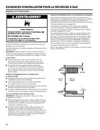
Page 40 - Exigences de l’emplacement; EXIGENCES D’INSTALLATION POUR LA SÉCHEUSE À GAZ
40 La sécheuse peut être installée dans un sous-sol, une salle de buanderie ou un encastrement.Il faut aussi prendre en compte les exigences d’emplacement des appareils voisins. IMPORTANT : Ne pas installer ou remiser la sécheuse dans un endroit où elle sera exposée aux intempéries. C’est à l’utilis...
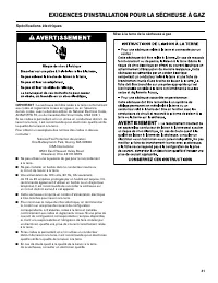
Page 41 - Mise à la terre de la sécheuse à gaz; Spécifications électriques
41 EXIGENCES D’INSTALLATION POUR LA SÉCHEUSE À GAZ Mise à la terre de la sécheuse à gaz IMPORTANT : La sécheuse doit être reliée à la terre conformément aux codes et règlements locaux en vigueur, ou en l'absence de tels codes, avec la dernière édition du National Electrical Code, ANSI/NFPA 70, ou du...
Page 42 - Alimentation en gaz
42 EXIGENCES D’INSTALLATION POUR LA SÉCHEUSE À GAZ IMPORTANT : Observer les dispositions de tous les codes et règlements en vigueur.L’installation doit satisfaire aux critères de tous les codes et règlements locaux. En l’absence de code local, l’installation doit satisfaire aux prescriptions de la n...
Page 43 - EXIGENCES D’INSTALLATION POUR LA SÉCHEUSE ÉLECTRIQUE
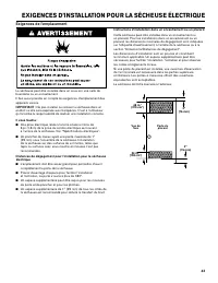
43 La sécheuse peut être installée dans un sous-sol, une salle de buanderie ou un encastrement.Il faut aussi prendre en compte les exigences d’emplacement des appareils voisins. IMPORTANT : Ne pas installer ou remiser la sécheuse dans un endroit où elle sera exposée aux intempéries. C’est à l’utilis...
Page 44 - INSTRUCTIONS DE LIAISON À LA TERRE
44 Spécifications électriques C’est à l’utilisateur qu’incombe la responsabilité de : ■ Communiquer avec un électricien qualifié. ■ S’assurer que les connexions électriques sont adéquates et conformes au Code canadien de l’électricité, C22.1 – dernière édition et à tous les codes locaux. Pour obteni...
Page 45 - EXIGENCES CONCERNANT L’ÉVACUATION DE LA SÉCHEUSE
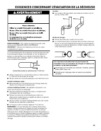
45 EXIGENCES CONCERNANT L’ÉVACUATION DE LA SÉCHEUSE AVERTISSEMENT : Pour réduire le risque d’incendie, cette sécheuse doit ÉVACUER L’AIR À L’EXTÉRIEUR. IMPORTANT : Observer les dispositions de tous les codes et règlements en vigueur. Le conduit d’évacuation de la sécheuse ne doit pas être raccordé à...
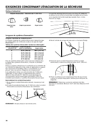
Page 46 - Hottes d’extraction; Longueur du système d’évacuation
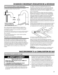
46 12" min. (305 mm) Clapets d’évacuation – Diamètre de 4" (102 mm) Clapet de type Clapet à persiennes Clapet incliné boîte Hottes d’extraction EXIGENCES CONCERNANT L’ÉVACUATION DE LA SÉCHEUSE Le clapet de décharge doit se trouver à au moins 12" (305 mm) au-dessus du sol ou de tout autre...
Page 47 - Raccordement à la canalisation de gaz; RACCORDEMENT À LA CANALISATION DE GAZ; Si on ne peut pas utiliser de clapet d’évacuation
47 1. Raccorder la canalisation de gaz à la sécheuse. Utiliser un composé d’étanchéité compatible avec le type de gaz utilisé. Si un conduit métallique flexible est utilisé, vérifier qu’il n’est pas déformé. Raccordement à la canalisation de gaz RACCORDEMENT À LA CANALISATION DE GAZ L’extérieur du c...
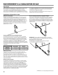
Page 48 - Type de gaz; Canalisation d’alimentation en gaz
48 Cette sécheuse est équipée pour une alimentation au gaz naturel. Sa conception est homologuée par CSA International pour l’alimentation au gaz de pétrole liquéfié (propane ou butane), avec conversion appropriée. Ne pas entreprendre de convertir la sécheuse pour une utilisation avec un gaz différe...
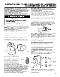
Page 49 - INSTALLATION DES PIEDS DE NIVELLEMENT, DE LA GLISSIÈRE À
49 2. Vissage des pieds de nivellement Examiner les pieds de nivellement pour trouver le repère en forme de diamant. Introduire manuellement les pieds dans les trous des pieds. Utiliser une clé à molette ou une clé de 1" (25 mm) pour faire tourner les pieds jusqu’à ce que la marque de repérage (...
Page 50 - NIVELLEMENT
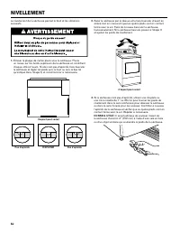
50 1. Enlever la plaque de carton placé sous la sécheuse. Placer un niveau sur les bords supérieurs de la sécheuse en contrôlant chaque côté et l’avant. Si elle n’est pas d’aplomb, faire basculer la sécheuse et régler les pieds vers le haut ou vers le bas tel qu’indiqué dans l’étape 3, et recommence...
Page 51 - ACHEVER L’INSTALLATION
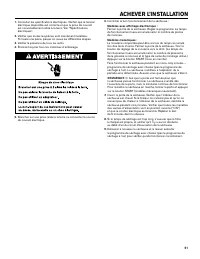
51 1. Consulter les spécifications électriques. Vérifier que la tension électrique disponible est correcte et que la prise de courant est convenablement reliée à la terre. Voir “Spécifications électriques”. 2. Vérifier que toutes les pièces sont maintenant installées. S’il reste une pièce, passer en...
Page 52 - INVERSION DU SENS D’OUVERTURE DE LA PORTE (FACULTATIF); Retirer l’assemblée de porte
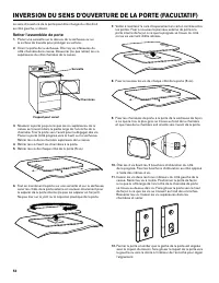
52 INVERSION DU SENS D’OUVERTURE DE LA PORTE (FACULTATIF) 9. Fixer les charnières de porte à la porte de la sécheuse de façon à ce que le trou le plus gros se trouve au fond de la charnière et que l’axe de la charnière soit orienté vers l’avant de la porte. 10. Ôter les 4 vis fixant les 2 bouchons d...
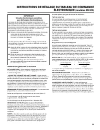
Page 55 - Informations générales d’utilisation
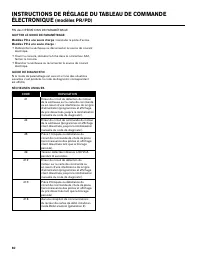
55 prix de l’appoint prix du programme complet Durée de l’appoint durée du programme complet = INSTRUCTIONS DE RÉGLAGE DU TABLEAU DE COMMANDE ÉLECTRONIQUE (modèles PR/PD) Informations générales d’utilisation AFFICHAGE VIDE – Cette situation indique que la sécheuse ne fonctionne pas. Entrer au mode d...
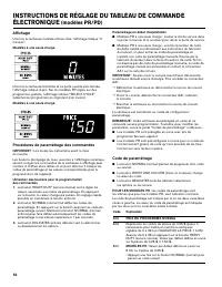
Page 56 - Code de paramétrage; Affichage
56 INSTRUCTIONS DE RÉGLAGE DU TABLEAU DE COMMANDE ÉLECTRONIQUE (modèles PR/PD) Paramétrage en début d’exploitation ■ Modèles PD à une seule charge : insérer la clé de service dans la porte, la tourner et la soulever pour retirer la porte de service. ■ Modèles PR à une seule charge : une fois le lect...


 Maytag MDE20PRAYW
User Manual
Maytag MDE20PRAYW
User Manual
 Maytag MDE28PDCYW
User Manual
Maytag MDE28PDCYW
User Manual
 Maytag MDG20MNBWW
User Manual
Maytag MDG20MNBWW
User Manual
 Maytag MED4500MW
User Manual
Maytag MED4500MW
User Manual
 Maytag MED5030MW
User Manual
Maytag MED5030MW
User Manual
 Maytag MED5430MW
User Manual
Maytag MED5430MW
User Manual
 Maytag MED5630HC
User Manual
Maytag MED5630HC
User Manual
 Maytag MED5630HW
User Manual
Maytag MED5630HW
User Manual
 Maytag MED5630MBK
User Manual
Maytag MED5630MBK
User Manual
 Maytag MED6200KW
User Manual
Maytag MED6200KW
User Manual