Page 2 - TABLE OF CONTENTS; IMPORTANT SAFETY INSTRUCTIONS
2 TABLE OF CONTENTS IMPORTANT SAFETY INSTRUCTIONS ................................... 2SAFETY GUIDELINES - DEFINITIONS .................................... 3GENERAL SAFETY RULES ...................................................... 3ADDITIONAL SPECIFIC SAFETY RULES ............................... 4...
Page 4 - SAvE ThESE INSTRUCTIONS.; AddITIONAL SPECIFIC SAFETY RULES
4 14. Keep safety guards in place at all times when the machine is in use. If removed for maintenance purposes, use extreme caution and replace the guards immediately when maintenance is complete. 15. Make sure the tool is firmly secured to the floor before use. 16. Check damaged parts. Before furth...
Page 5 - POwER CONNECTIONS; MOTOR SPECIFICATIONS
5 A separate electrical circuit should be used for your machines. This circuit should not be less than #12 wire and should be protected with a 20 Amp time lag fuse. If an extension cord is used, use only 3-wire extension cords which have 3-prong grounding type plugs and matching receptacle which wil...
Page 6 - ExTENSION CORdS
6 ExTENSION CORdS U s e p r o p e r e x t e n s i o n c o r d s . Make sure your extension cord is in good condition and is a 3-wire extension cord which has a 3-prong grounding type plug and m a t c h i n g re c e p t a c l e w h i c h w i l l a c c e p t t h e machine’s plug. when using an extensi...
Page 7 - kEY FEATURES ANd COMPONENTS; FUNCTIONAL dESCRIPTION
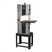
7 kEY FEATURES ANd COMPONENTS FIg. 1 A. Blade Tensioning knob B. Upper wheel guard C. Power Switch d. Cast Iron Tilting Table E. Blade guide Assembly F. Miter gauge T-Slot g. Lower wheel guard h. 1 hP Motor I. Belt Tensioning handle j. Tool Stand FUNCTIONAL dESCRIPTION The DELTA ® 14" Steel Fram...
Page 8 - CONTENTS OF STANd
8 Carefully unpack the machine and all loose items from the shipping container(s). Remove the rust-preventative oil from unpainted surfaces using a soft cloth moistened with mineral spirits, paint thinner or denatured alcohol.Do not use highly volatile solvents such as gasoline, naphtha, acetone or ...
Page 9 - ASSEMBLY; STANd ASSEMBLY; SECURE TABLE TO TABLE TRUNNION SYSTEM; ATTAChINg ThE SAw TO ThE STANd
9 FIgURE 2 ASSEMBLY STANd ASSEMBLY Refer to Figure 2 • Place top surface (A) upside down on a level surface. Attach the four legs (B) to the top using M6 X 16 carriage bolts, M6 flat washers, and M6 hex nuts. • Attach bottom rail supports (C) using M6 X 16 carriage bolts, M6 flat washers, and M6 hex...
Page 10 - INSTALL BLAdE TENSIONINg kNOB; INSTALL BANd SAw BLAdE
10 ASSEMBLY INSTALL BLAdE TENSIONINg kNOB • Fit the blade tensioning knob (A) onto the blade tensioning spindle (B) located at the top of the machine. FIgURE 5 INSTALL BANd SAw BLAdE • Open the upper and lower cabinets of the saw by turning the cabinet lock knobs (A) clockwiseSee Figure 6. • Locate ...
Page 11 - AdjUST ThE BLAdE TRACkINg; INSERT ThROAT PLATE; SQUARE TABLE TO BLAdE
11 ASSEMBLY AdjUST ThE BLAdE TRACkINg FIgURE 9 INSERT ThROAT PLATE FIgURE 10 See Figure 9. disconnect the machine from the power source before making any adjustments!IMPORTANT: Before tracking the blade, confirm that the blade guides and blade support bearings are clear of the blade. • After applyin...
Page 12 - OPERATION; STARTINg ANd STOPPINg ThE SAw
12 OPERATION STARTINg ANd STOPPINg ThE SAw Make sure that the switch is in the “OFF" position before plugging cord into outlet. Do not touch the plug’s metal prongs when unplugging or plugging in the cord Do not attempt to operate this tool w i t h o u t f i r s t c o n n e c t i n g i t t o a n...
Page 13 - TILTINg ThE TABLE; POSITIONINg ThE UPPER BLAdE gUIdE
13 OPERATION TILTINg ThE TABLE disconnect the machine from the power source! See Figure 14. You can tilt the band saw table up to 45° to the right. To tilt the table to the right. • Loosen the black table tilt locking wing nut (A), located underneath the lower trunnion. • Tilt the table to the desir...
Page 14 - CUTTINg CURvES; AdjUSTMENTS; AdjUSTINg ThE BLAdE TENSION
14 OPERATION CUTTINg CURvES Turn the stock carefully so that the blade follows without twisting. For very abrupt curves, consider using a narrower blade, or a blade with more set. Another solution to this problem is to make relief cuts (Figure 16) When you withdraw the workpiece or change the cut, b...
Page 15 - AdjUSTINg ThE BLAdE gUIdES ANd BEARINgS; SIdE BEARINgS; AdjUSTINg BLAdE TRACkINg; REAR BEARINgS
15 AdjUSTMENTS AdjUSTINg ThE BLAdE gUIdES ANd BEARINgS See Figure 18. disconnect the machine from the power source before making any adjustments! Adjust the upper blade guides and blade support bearings only after the blade has the correct tension and is tracking properly.The DELTA ® 14" Steel F...
Page 16 - MAINTENANCE; kEEP MAChINE CLEAN; FAILURE TO START; TROUBLEShOOTINg
16 MAINTENANCE STARTINg ANd STOPPINg ThE SAw Make sure that the switch is in the "OFF" postion. To reduce the risk of injury, turn unit off and disconnect it from power source before installing and removing accessories, before adjusting or when making repairs.An accidental start-up can cause...
Page 18 - ACCESSORIES; Five Year Limited New Product warranty; wARRANTY
18 ACCESSORIES A complete line of accessories is available from your DELTA ® Supplier, DELTA ® Factory Service Centers, and DELTA ® Factory Service Centers, and DELTA ® Authorized Service Centers. Please visit our Web Site www. DeltaMachinery.com for an online catalog or for the name or your nearest...
Page 19 - PARTS, SERVICE OR WARRANTY ASSISTANCE; REPLACEMENT PARTS; FREE WARNING LABEL REPLACEMENT
19 PARTS, SERVICE OR WARRANTY ASSISTANCE All DELTA ® machines and accessories are manufactured to high quality standards and are serviced by a network of DELTA ® Factory Service Centers and DELTA ® Authorized Service Centers. To obtain additional information regarding your DELTA ® quality product or...
Page 21 - RÈgLES dE SÉCURITÉ gÉNÉRALES
21 RÈgLES dE SÉCURITÉ gÉNÉRALES LE NON-RESPECT dE CES RÈgLES PEUT ENTRAÎNER dES BLESSURES PERSONNELLES gRAvES. • POUR vOTRE PROPRE SÉCURITÉ, ASSUREZ-vOUS d’AvOIR BIEN LU ET COMPRIS LE MANUEL d’UTILISATION AvANT dE FAIRE FONCTIONNER L’APPAREIL. Apprenez à connaître son domaine d’utilisation et ses li...
Page 22 - CONSERvEZ CES CONSIgNES.; RÈgLES dE SÉCURITÉ SPÉCIFIQUES SUPPLÉMENTAIRES
22 17. Prévoyez un espace suffisant autour de la zone de travail et un éclairage en plongée non éblouissant. 18. Gardez le plancher autour de l’appareil propre et exempt de débris, d’huile et de graisse. 19. Gardez les visiteurs à une distance sécuritaire de la zone de travail. Tenez les enfants à d...
Page 23 - RACCORdEMENTS ÉLECTRIQUES; SPÉCIFICATIONS dU MOTEUR
23 FIg. A FIg. B BROChES PORTEUSES dE COURANT LA BROChE dE MISE À LA TERRE EST LA PLUS LONgUE dES TROIS BOÎTE dE COURANT dE MISE À LA TERRE BOÎTE dE COURANT dE MISE À LA TERRE MOYENS dE MISE À LA TERRE AdAPTATEUR Un circuit électrique séparé devrait être utilisé pour vos appareils. Les fils du circu...
Page 24 - RALLONgES
24 RALLONgES U t i l i s e z d e s r a l l o n g e s appropriées. Assurez-vous que la r a l l o n g e e s t e n b o n é t a t e t q u ’ i l s ’ a g i t d ’ u n e rallonge à trois fils avec une fiche de mise à la t e r r e à t r o i s b r o c h e s e t d ’ u n r é c e p t a c l e correspondant à la f...
Page 25 - CARACTÉRISTIQUES ET COMPOSANTES; dESCRIPTION dU FONCTIONNEMENT
25 CARACTÉRISTIQUES ET COMPOSANTES FIgURE 1 A. Poignée de tension de la lame B. garde-roue supérieur C. Interrupteur d. Table en fonte inclinable E. Ensemble de guide de lame F. Rainure en T pour guide à onglets g. garde-roue inférieur h. Moteur 1 hP I. Poignée de tension de la courroie j. Support d...
Page 26 - CONTENU dU PACk
26 Déballez minutieusement l’appareil et toutes les pièces détachées de la ou des boîtes d’expédition. Retirez l'huile anti-corrosion des surfaces non peintes avec un chiffon doux humidifié de spiritueux minéraux, de diluant de peinture ou d'alcool dénaturé.N'utilisez pas de solvants hautement volat...
Page 27 - MONTAgE; MONTAgE dU SUPPORT; FIxER LA TABLE AU SYSTÈME dE TOURILLONS dE TABLE; FIxER LA SCIE AU SUPPORT
27 FIgURE 2 MONTAgE MONTAgE dU SUPPORT Consultez la Figure 2 • Placez la surface supérieure (A) à l'envers sur une surface plane. Fixez les quatre pieds (B) au sommet avec 16 boulons de carrosserie M6, des rondelles plates M6 et des écrous hexagonaux M6. • Fixez les supports de rails inférieurs (C) ...
Page 28 - INSTALLER LA POIgNÉE dE TENSION; INSTALLER LA LAME dE LA SCIE À RUBAN
28 MONTAgE INSTALLER LA POIgNÉE dE TENSION dE LA LAME voir Figure 5. • Placez la poignée de tension de la lame (A) sur la broche de serrage de la lame (B) située au sommet de l'appareil. FIgURE 5 INSTALLER LA LAME dE LA SCIE À RUBAN REMARQUE : la lame de votre scie à ruban avec struc- ture en acier ...
Page 29 - RÉgLER LE SUIvI dE LA LAME; INSÉRER LA PLAQUE LUMIÈRE; ALIgNER LA TABLE ET LA LAME
29 MONTAgE RÉgLER LE SUIvI dE LA LAME FIgURE 9 INSÉRER LA PLAQUE LUMIÈRE FIgURE 10 voir Figure 9. débranchez l’appareil de la source d’alimentation avant de faire des ajustements! IMPORTANT : avant le suivi de la lame, vérifiez que les guides de lame et paliers de support de lame sont à l'écart de l...
Page 30 - FONCTIONNEMENT; dÉMARRAgE ET ARRÊT dE LA SCIE
30 FONCTIONNEMENT dÉMARRAgE ET ARRÊT dE LA SCIE Assurez-vous que l’interrupteur est à la position « OFF » (Arrêt) avant de brancher le cordon dans la prise. Ne touchez pas aux broches métalliques de la fiche au moment de brancher ou de débrancher le cordon. N e f a i t e s p a s f o n c t i o n n e ...
Page 31 - INCLINER LA TABLE; POSITIONNER LE gUIdE dE LAME SUPÉRIEUR
31 FONCTIONNEMENT INCLINER LA TABLE déconnectez l'appareil de la source d'alimentation! voir Figure 14. Vous pouvez incliner la table de la scie à ruban de 45° vers la droite. Pour incliner la table vers la droite : • Desserrez le papillon de serrage d'inclinaison de la table noir (A) situé sous le ...
Page 32 - COUPER dES COURBES; AjUSTEMENTS; RÉgLER LA TENSION dE LA LAME
32 FONCTIONNEMENT COUPER dES COURBES Tour nez le matériel avec précautions afin que la lame suive sans se tordre. Pour les courbes très prononcées, envisagez d'utiliser une lame plus étroite ou avec plus d'inclinaison. Une autre solution à ce problème est de faire des coupes en relief (Figure 16) Lo...
Page 33 - RÉgLER LES gUIdES dE LAME ET PALIERS; PALIERS LATÉRAUx; RÉgLER LE SUIvI dE LAME; PALIERS ARRIÈRE
33 AjUSTEMENTS RÉgLER LES gUIdES dE LAME ET PALIERS voir Figure 18. débranchez l’appareil de la source d’alimentation avant de faire des ajustements! Réglez les guides de lame supérieurs et les paliers de support de lame uniquement quand la lame a la bonne tension et avance correctement.La scie à ru...
Page 34 - ENTRETIEN; gARdER L’APPAREIL PROPRE; ÉChEC dU dÉMARRAgE; dÉPANNAgE
34 ENTRETIEN dÉMARRAgE ET ARRÊT dE LA SCIE Assurez-vous que l'interrupteur est en position « OFF » (Arrêt). Pour réduire le risque de blessure, éteignez l'appareil et déconnectez-le de la source d'alimentation avant d'installer et de retirer les accessoires, avant le réglage ou lors des réparations....
Page 36 - garantie limitée de cinq ans pour les produits neufs; À PROPOS dES LAMES dE SCIE À RUBAN
36 ACCESSOIRES gARANTIE Une gamme complète d’accessoires peut être obtenue auprès de votre fournisseur DELTA MD , des centres de service du fabricant DELTA MD , et des centres de services agréés DELTA MD . Rendez-vous sur notre site Web www.DeltaMachinery.com pour obtenir un catalogue en ligne ou po...
Page 37 - AIDE POUR LES PIÈCES, LE SERVICE OU LA GARANTIE; PIÈCES DE RECHANGE
37 AIDE POUR LES PIÈCES, LE SERVICE OU LA GARANTIE Tous les appareils et accessoires DELTA MD sont fabriqués selon des normes de qualité élevées et sont soutenus par un réseau de centres de service du fabricant DELTA MD et des centres de services DELTA MD autorisés. Pour en savoir davantage sur votr...
Page 39 - REgLAS gENERALES dE SEgURIdAd
39 REgLAS gENERALES dE SEgURIdAd N O S E g U I R E S TA S R E g L A S d E S E g U R I d A d P U E d E O C A S I O N A R L E S I O N E S PERSONALES gRAvES. • POR SU PROPIA SEgURIdAd, LEA Y COMPRENdA EL MANUAL dE INSTRUCCIONES ANTES dE OPERAR LA UNIdAd. Conozca los usos y las limitaciones de la unidad...
Page 40 - gUARdE ESTAS INSTRUCCIONES.; REgLAS AdICIONALES dE SEgURIdAd
40 16. Examine las piezas dañadas. Antes de seguir u t i l i z a n d o l a m á q u i n a , d e b e e x a m i n a r s e cuidadosamente si el protector u otra pieza están dañados, para determinar que funcionarán adecuadamente y desempeñarán su función prevista. Examine la alineación de las piezas móvi...
Page 41 - CONExIONES dE ALIMENTACIÓN; ESPECIFICACIONES dEL MOTOR
41 Se debe utilizar un circuito eléctrico por separado para sus máquinas. Este circuito no debe ser inferior a un cable calibre 12 y debe estar protegido con un fusible con retardo de tiempo de 20 amperes. Si se utiliza un alargador eléctrico, use únicamente alargadores eléctricos trifilares con enc...
Page 42 - ALARgAdORES ELÉCTRICOS
42 ALARgAdORES ELÉCTRICOS Utilice los alargadores eléctricos adecuados. Cerciórese de que los alargadores eléctricos estén en buenas condiciones y de que sean del tipo de alargadores eléctricos con 3 cables que tienen un enchufe con conexión a tierra con 3 clavijas y un tomacorriente equivalente que...
Page 43 - CARACTERÍSTICAS Y COMPONENTES CLAvE; dESCRIPCIÓN FUNCIONAL
43 CARACTERÍSTICAS Y COMPONENTES CLAvE FIgURA 1 A. Perilla tensionadora de la hoja B. guarda de la rueda superior C. Interruptor eléctrico d. Mesa basculante de hierro fundido E. Ensamble de guía de la hoja F. Ranura en T para calibre de inglete g. guarda de la rueda inferior h. Motor de 1 hP I. Man...
Page 45 - ENSAMBLAjE; ENSAMBLAjE dE LA BASE; SUjETE LA MESA AL SISTEMA dE MUÑONES dE MESA; INSTALE LA SIERRA EN LA BASE
45 FIgURA 2 ENSAMBLAjE ENSAMBLAjE dE LA BASE Consulte la Figura 2 • Coloque la superficie superior (A) boca abajo en una superficie nivelada. Coloque las cuatro patas (B) en la parte superior con pernos cabeza redonda cuello cuadrado M6 X 16, arandelas planas M6 y tuercas hexagonales M6. • Coloque l...
Page 46 - INSTALE LA PERILLA; INSTALE LA hOjA dE LA SIERRA CINTA
46 ENSAMBLAjE INSTALE LA PERILLA TENSIONAdORA dE LA hOjA vea la figura 5. • Coloque la perilla tensionadora de la hoja (A) sobre el husillo tensionador de la hoja (B) localizado en la parte superior de la máquina. FIgURA 5 INSTALE LA hOjA dE LA SIERRA CINTA NOTA: La hoja de su sierra cinta de bastid...
Page 47 - AjUSTE dEL dESPLAZAMIENTO dE LA hOjA; INSERTE LA PLACA dE gARgANTA
47 ENSAMBLAjE AjUSTE dEL dESPLAZAMIENTO dE LA hOjA FIgURA 9 INSERTE LA PLACA dE gARgANTA FIgURA 10 vea la figura 9. Antes de realizar cualquier tipo de ajuste, desconecte la máquina de la fuente de alimentación. IMPORTANTE: Antes de ajustar el desplazamiento de la hoja, confirme que las guías de la ...
Page 48 - FUNCIONAMIENTO; ENCENdER Y dETENER LA SIERRA
48 FUNCIONAMIENTO ENCENdER Y dETENER LA SIERRA Asegúrese de que el interruptor se encuentre en la posición “apagado” (off) antes de enchufar el cable de alimentación. No toque las clavijas metálicas del enchufe al desenchufar o enchufar el cable. No intente operar esta herramienta sin conectarla pri...
Page 49 - INCLINACIÓN dE LA MESA; POSICIONAMIENTO dE LA gUÍA dE LA hOjA SUPERIOR
49 FUNCIONAMIENTO INCLINACIÓN dE LA MESA desconecte la máquina de la alimentación eléctrica. vea la figura 14. Puede inclinar la mesa de la sierra cinta hasta 45° a la derecha. Para inclinar la mesa hacia la derecha: • Afloje la tuerca mariposa negra de seguridad de inclinación de la mesa (A) locali...
Page 50 - CORTE dE CURvAS; AjUSTES; AjUSTE dE LA TENSIÓN dE LA hOjA
50 FUNCIONAMIENTO CORTE dE CURvAS Gire el material cuidadosamente para que la hoja siga sin torcerse. Para curvas muy abruptas, considere el uso de una hoja más angosta o una hoja con más fijación. Otra solución a este problema es hacer cortes de alivio (figura 16). Al retirar la pieza de trabajo o ...
Page 51 - AjUSTE dE LAS gUÍAS Y LOS ROdAMIENTOS dE LA hOjA; ROdAMIENTOS LATERALES; AjUSTE dEL dESPLAZAMIENTO; ROdAMIENTOS TRASEROS
51 AjUSTES AjUSTE dE LAS gUÍAS Y LOS ROdAMIENTOS dE LA hOjA vea la figura 18. Antes de realizar cualquier tipo de ajuste, desconecte la máquina de la fuente de alimentación. Ajuste las guías superiores de la hoja y los rodamientos de soporte de la hoja únicamente después de que la hoja tenga la tens...
Page 52 - MANTENIMIENTO; MANTENgA LA MÁQUINA LIMPIA; FALLA EN EL ENCENdIdO; RESOLUCIÓN dE PROBLEMAS
52 MANTENIMIENTO ENCENdER Y dETENER LA SIERRA Asegúrese de que el interruptor esté en la posición de apagado. Para reducir el riesgo de lesiones, apague la unidad y desconéctela de la alimentación eléctrica antes de instalar y remover accesorios, antes de realizar ajustes o al hacer reparaciones.Un ...
Page 54 - garantía de producto nuevo limitada a cinco años; ACCESORIOS; ACERCA dE LAS hOjAS PARA SIERRA CINTA
54 garantía de producto nuevo limitada a cinco años dELTA ® reparará o sustituirá, a su cargo y opción, cualquier nueva máquina, repuesto o accesorio de la máquina dELTA ® que, en condiciones normales de utilización, ha demostrado ser defectuoso en mano de obra o material, siempre que el cliente dev...
Page 55 - ASISTENCIA SOBRE GARANTÍA, SERVICIO O PIEZAS; PIEZAS DE REPUESTO
55 ASISTENCIA SOBRE GARANTÍA, SERVICIO O PIEZAS Todas las máquinas y accesorios DELTA ® están fabricados en cumplimiento de altos estándares de calidad y reciben el servicio técnico de una red de centros de servicio de fábrica de DELTA ® y centros de servicio autorizados de DELTA ® . Para obtener in...
Page 56 - 9 Roush Street
99 Roush Street Anderson, SC 29625 (800) 223-7278 www.DeltaMachinery.com Copyright © 2013 DELTA ® Power Equipment Corporation DPEC002265 - 12-10-13


 Delta 3KVA Manual
 Delta 10A Manual
 Delta 11-950 Manual
 Delta 11-985 Manual
 Delta 11-990 Manual
 Delta 14-651 Manual
 Delta 17-900 Manual
 Delta 17-925 Manual
 Delta 17-950L Manual
 Delta 18-900L Manual
 Delta 22-540 Manual
 Delta 22-555 Manual
 Delta 22-590 Manual
 Delta 22-590X User Manual
 Delta 23-196 Manual
 Delta 23-197 Manual
 Delta 23-580 Manual
 Delta 23-592 Manual
 Delta 23-640 Manual