Yamaha DVD-S2300 - Manuals
Yamaha DVD-S2300 Player – Manual, User Manual in PDF format online.
Manuals:
Manual Yamaha DVD-S2300
1

2

3

4

5

6

7

8

9

10

11

12

13

14

15

16

17

18

19

20

21

22

23

24

25

26

27

28

29

30

31

32

33

34

35

36

37

38

39

40

41

42

User Manual Yamaha DVD-S2300
1

2

3

4

5

6

7

8

9

10

11

12

13

14

15

16

17

18

19

20

21

22

23

24

25

26

27

28

29

30

31

32

33

34

35

36

37

38

39

40

41

42

43

44

45

46

47

48

49

50

51

52

53

54

55

56

57

58

59

60

61

62

63

64

65

66

67

68

69

70

71

72

73

74

75

76

77

78

79

80

81

82

83

84

85

86

87

88

89

90

91

92

93

94

95

96

97

98

99

100

101

102

103

104

105

106

Summary
Page 3 - Laser Diode Properties; Semiconductor laser GaAlAs; WARNING
DVD-S2300 3 DVD-S2300 Laser Diode Properties Type: Semiconductor laser GaAlAs Wave length: 658 nm (DVD)790 nm (VCD/CD) Output Power: CLASS II a 1mW (DVD) CLASS I 1mW (VCD/CD) VARO! : AVATTAESSA JA SUOJALUKITUS OHITETTAESSA OLET ALTTIINA NÄKYMÄTTÖMÄLLE LASER-SÄTEILYLLE. ÄLÄ KATSO SÄTEESEEN. VARNING! ...
Page 4 - PREVENTION OF ELECTRO STATIC DISCHARGE; Grounding for Electrostatic Damage Prevention; Worktable grounding; Handling of the Optical Pickup; LOCALE MANAGEMENT INFORMATION
DVD-S2300 4 DVD-S2300 ■ PREVENTION OF ELECTRO STATIC DISCHARGE The laser diode in the traverse unit (optical pickup) may be damaged due to static electricity from clothes or the human body.Use caution to prevent electrostatic damage when servicing or handling the laser diode. 1. Grounding for Electr...
Page 6 - REAR PANELS; U model
DVD-S2300 6 DVD-S2300 ■ REAR PANELS U model A model B, G models J model
Yamaha Players Manuals
-
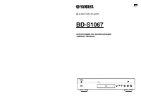 Yamaha BD-S1067
User Manual
Yamaha BD-S1067
User Manual
-
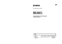 Yamaha BD-S671
User Manual
Yamaha BD-S671
User Manual
-
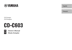 Yamaha CD-C603BL
User Manual
Yamaha CD-C603BL
User Manual
-
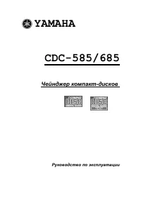 Yamaha CDC-685
Manual
Yamaha CDC-685
Manual
-
 Yamaha CDR-D651
Manual
Yamaha CDR-D651
Manual
-
 Yamaha CDR-HD1300
Manual
Yamaha CDR-HD1300
Manual
-
 Yamaha CD-S300
User Manual
Yamaha CD-S300
User Manual
-
 Yamaha CD-S303BL
User Manual
Yamaha CD-S303BL
User Manual
-
 Yamaha CDX-397MK2
User Manual
Yamaha CDX-397MK2
User Manual
-
 Yamaha DVD-S1800
User Manual
Yamaha DVD-S1800
User Manual
-
Yamaha DVD-S1800
Manual
-
 Yamaha DVD-S530
Manual
Yamaha DVD-S530
Manual
-
 Yamaha DVD-S663
User Manual
Yamaha DVD-S663
User Manual
-
Yamaha DVD-S663
Manual
-
 Yamaha GT-5000
User Manual
Yamaha GT-5000
User Manual
-
 Yamaha TT-S303BL
User Manual
Yamaha TT-S303BL
User Manual
-
 Yamaha DVD-S796
Manual
Yamaha DVD-S796
Manual