WEN BG4280 - Manuals
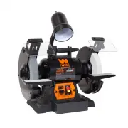
User Manual WEN BG4280


Summary
4280 120V, 60 Hz, 5A 2000 to 3400 RPM 8 inches x 1 inch 5/8 inch #36 and #80 41 pounds 17 x 18.1 x 13 inches TABLE OF CONTENTS Technical Data 234678910121315 General Safety RulesSpecific Safety Rules For Bench GrinderElectrical InformationKnow Your Bench Grinder OperationMaintenance Exploded View an...
3 GENERAL SAFETY RULES Safety is a combination of common sense, staying alert and knowing how your item works. SAVE THESE SAFE- TY INSTRUCTIONS. WARNING: To avoid mistakes and serious injury, do not plug in your tool until the following steps have been read and understood. 1. READ and become familia...
4 15. DO NOT OVERREACH. Keep proper footing and balance at all times. Wear oil-resistant rubber-soled foot-wear. Keep the floor clear of oil, scrap, and other debris. 16. MAINTAIN TOOLS PROPERLY. ALWAYS keep tools clean and in good working order. Follow instruc-tions for lubricating and changing acc...
WEN Grinding Machines Manuals
-
 WEN 6321
User Manual
WEN 6321
User Manual
-
 WEN 6369
User Manual
WEN 6369
User Manual
-
 WEN 6377
User Manual
WEN 6377
User Manual
-
 WEN 6524
User Manual
WEN 6524
User Manual
-
 WEN 20401
User Manual
WEN 20401
User Manual
-
 WEN 6502T
User Manual
WEN 6502T
User Manual
-
 WEN 6510T
User Manual
WEN 6510T
User Manual
-
 WEN 6515T
User Manual
WEN 6515T
User Manual
-
 WEN AT1305
User Manual
WEN AT1305
User Manual
-
 WEN AT6535
User Manual
WEN AT6535
User Manual
-
 WEN BG4260
User Manual
WEN BG4260
User Manual
-
 WEN BG4276
User Manual
WEN BG4276
User Manual
-
 WEN BG4286
User Manual
WEN BG4286
User Manual
-
 WEN BG625V
User Manual
WEN BG625V
User Manual
-
 WEN DW6395
User Manual
WEN DW6395
User Manual
-
 WEN HB424V
User Manual
WEN HB424V
User Manual
-
 WEN HB6319
User Manual
WEN HB6319
User Manual
-
 WEN HB632V
User Manual
WEN HB632V
User Manual