MSI Z490-A PRO - Manuals
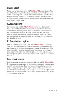
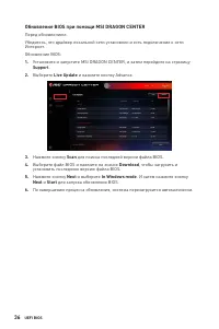
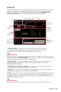
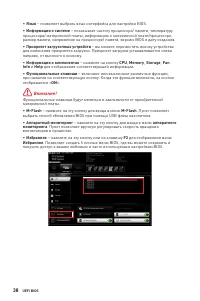
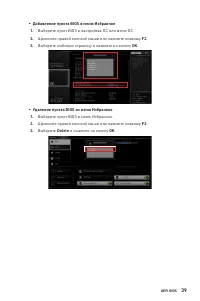
User Manual MSI Z490-A PRO
1
2
3
4
5
6

7
8
9
10
11
12
13
14
15
16
17
18
19
20
21
22

23
24
25
26
27
28
29
30

31
32
33
34
35
36
37
38
39
40
41
42
43
44
45

46
47
48
49
50
51
52
53
54
55
56
57
58
59
60
61
62
63
64
65
66
67
68
69
70
71

72
73

74
75
76
77
78
79
80
81
82
83
84
85
86
87
88
89
90
91
92
93
94
95
96
97
98
99
100

101
102
103
104
105
106
107
108
109
110
111

112
113
114
115
116
117

118
119
120

121

122
123

124
125
126
127
128
129

130
131
132
133
134
135
136
137
138
139
140
141
142
143
144
145
146

147
148
149
150
151
152
153
154
155
156
157
158
159

160

161
162
163
164
165
166
167
168
169
170

171
172
173
174
175

176
177
178
179
180
181
182
183
184
185
186
187
188
189
190
191
192

193
194
195
196
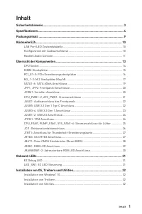
Summary
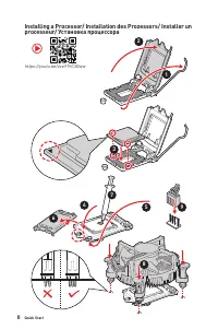
Page 2 - II; processeur/ Установка процессора
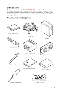
II Quick Start Installing a Processor/ Installation des Prozessors/ Installer un processeur/ Установка процессора ⚽ https://youtu.be/4ce91YC3Oww 1 2 3 6 4 5 7 8 9
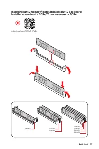
Page 3 - III; Installer une mémoire DDR4/ Установка памяти DDR4
III Quick Start Installing DDR4 memory/ Installation des DDR4-Speichers/ Installer une mémoire DDR4/ Установка памяти DDR4 http://youtu.be/T03aDrJPyQs ⚽ DIMMA2 DIMMA2 DIMMB2 DIMMA1 DIMMA2 DIMMB1 DIMMB2
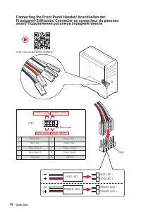
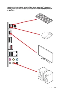
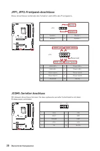
Page 4 - IV; Connecting the Front Panel Header/ Anschließen der; HDD LED
IV Quick Start Connecting the Front Panel Header/ Anschließen der Frontpanel-Stiftleiste/ Connecter un connecteur du panneau avant/ Подключение разъемов передней панели http://youtu.be/DPELIdVNZUI HDD LED RESET SW JFP1 HDD LED HDD LED - HDD LED + POWER LED - POWER LED + POWER LED 1 2 10 9 + + + - - ...
MSI Motherboards Manuals
-
 MSI A320M-A PRO
User Manual
MSI A320M-A PRO
User Manual
-
 MSI A520
User Manual
MSI A520
User Manual
-
 MSI A520M-A PRO
User Manual
MSI A520M-A PRO
User Manual
-
 MSI B450M-A PRO
User Manual
MSI B450M-A PRO
User Manual
-
 MSI B460
User Manual
MSI B460
User Manual
-
 MSI B550-A PRO
User Manual
MSI B550-A PRO
User Manual
-
 MSI B550M PRO-VDH
User Manual
MSI B550M PRO-VDH
User Manual
-
 MSI B560
User Manual
MSI B560
User Manual
-
 MSI B560-A PRO
User Manual
MSI B560-A PRO
User Manual
-
 MSI B560M BOMBER
User Manual
MSI B560M BOMBER
User Manual
-
 MSI B560M PRO-E
User Manual
MSI B560M PRO-E
User Manual
-
 MSI B660
User Manual
MSI B660
User Manual
-
 MSI B660M
User Manual
MSI B660M
User Manual
-
 MSI H510
User Manual
MSI H510
User Manual
-
 MSI H510M-A PRO
User Manual
MSI H510M-A PRO
User Manual
-
 MSI H610
User Manual
MSI H610
User Manual
-
 MSI MAG B550
User Manual
MSI MAG B550
User Manual
-
 MSI MAG B550M
User Manual
MSI MAG B550M
User Manual
-
 MSI MAG B650M
User Manual
MSI MAG B650M
User Manual
-
 MSI MAG Z690
User Manual
MSI MAG Z690
User Manual