Emerson 1F95EZ-0671 - Manuals

Emerson 1F95EZ-0671 Thermostat – User Manual, Manual in PDF format online.
Manuals:
User Manual Emerson 1F95EZ-0671


Summary
2 WARNING ! ATTENTION: MERCURY NOTICE This product does not contain mercury. However, this product may replace a product that contains mercury. Mercury and products containing mercury must not be discarded in household trash. Do not touch any spilled mercury. Wearing non-absorbent gloves, clean up a...
3 DHM 2 D H M HM 2 H M L SYST E M POWER RC R C LED On/Off to terminal connections on HVAC equipment Connect W/E W2 Y Y2 G O/B L DHM DHM2 HM2 HM RC To Return Air Sensor (RAS) Required W/E W2 Y Y2 G O/B L HM HM2 DHM SYS DRY SYS DHM2 RCRH R C DRY R and C from HVAC Terminal Strip or System Transformer Wi...
4 **T o use the HV A C transformer to power humidification/dehumidification switch HM/DHM switches to “SYS ” position: - Connect humidifier to HM - Connect dehumidifier to DHM If humidifier or dehumidifier has a separate transformer switch HM or DHM switch to “DRY” position : - Connect humidifier to HM and...
Manual Emerson 1F95EZ-0671


Summary
2 Remove Old Thermostat Before removing wires from old thermostat, mark wires for terminal identifi cation so the proper connections will be made to the new thermostat. Installing New Thermostat 1. Pull the thermostat body off the thermostat base. Forcing or prying on the thermostat will cause damag...
3 WIRING DIAGRAMS Figure 4 – Heat Pump Systems Figure 2 – Single Stage or Multi-Stage System (No Heat Pump) with Single Transformer Heat Pump 1 (HP1) Heat Pump 2 (HP2) O Energized in Cool Mode B Energized in Heat, Off, Emergency Mode NoOutput 2ndStage(Com-pressor) Heat andCool Mode1st Stage(Compress...
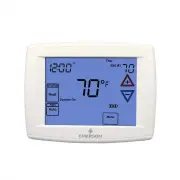
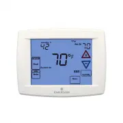
4 Programming and Confi guration Items 1 “Heat" “A/C” “Off” identi fi es button. When fi lled indi- cates system mode selected. 2 "Aux" inidicates thermostat con fi gured for Heat Pump. When fi lled indicates Auxiliary stage is operating. 3 "Adv Day" identi fi es button when in s...
Emerson Thermostats Manuals
-
 Emerson 1E78-144
User Manual
Emerson 1E78-144
User Manual
-
 Emerson 1F75P-21NP
User Manual
Emerson 1F75P-21NP
User Manual
-
 Emerson 1F78-151
User Manual
Emerson 1F78-151
User Manual
-
Emerson 1F78-151
Manual
-
 Emerson 1F80-361
User Manual
Emerson 1F80-361
User Manual
-
 Emerson 1F83C-11NP
User Manual
Emerson 1F83C-11NP
User Manual
-
 Emerson 1F83C-11PR
User Manual
Emerson 1F83C-11PR
User Manual
-
 Emerson 1F83H-21PR
User Manual
Emerson 1F83H-21PR
User Manual
-
 Emerson 1F85U-42NP
User Manual
Emerson 1F85U-42NP
User Manual
-
 Emerson 1F85U-42PR
User Manual
Emerson 1F85U-42PR
User Manual
-
 Emerson 1F86-344
User Manual
Emerson 1F86-344
User Manual
-
 Emerson 1F95-1277
User Manual
Emerson 1F95-1277
User Manual
-
Emerson 1F95-1277
Manual
-
 Emerson 1F97-1277
User Manual
Emerson 1F97-1277
User Manual
-
Emerson 1F97-1277
Manual
-
 Emerson P150
User Manual
Emerson P150
User Manual
-
 Emerson ST25
User Manual
Emerson ST25
User Manual
-
 Emerson ST55
User Manual
Emerson ST55
User Manual
-
 Emerson ST75
User Manual
Emerson ST75
User Manual