Emerson 1F83C-11PR - User Manual
Emerson 1F83C-11PR Thermostat – User Manual, read for free online in PDF format. We hope this helps you resolve any issues you may have. If you have further questions, please contact us through the contact form.


Table of Contents:
- Page 2 – INSTALLER MENU; Battery Location; TEST EQUIPMENT; There will be up to a; CAUTION
- Page 3 – THERMOSTAT OVERVIEW; USING THE THERMOSTAT; THERMOSTAT OPERATION; Set Current Time and Day; Note: Time icons will flash at initial power up or after a reset.; Day, but can be setup as a; until the icon appears (this can; USER MENU
- Page 4 – THERMOSTAT SCHEDULE; Energy Saving Factory Schedule; Modify the Heating Schedule; and return to home screen.; Modify the Cooling Schedule; TROUBLESHOOTING; Resetting the Thermostat or Thermostat Settings
Electrical Rating:
Battery Power ..................................... mV to
30
VAC, NEC Class II,
50/60
Hz
Input-Hardwire ....................................
20
to
30
VAC, NEC Class II,
50
/
60
Hz
Terminal Load ..........................................
1.0
A per terminal,
1.5
A maximum all terminals combined
Setpoint Range ........................................
45°
to
99°
F (
7°
to
37° C)
Rated Differentials: Fast
Med
Slow
Heat (@
6
°F/ Hr) ..................................
0.5°F 0.75°F 1.9°F
Cool (@
6
°F/ Hr) ..................................
0
.
9°F 1.2°F 1.7°F
Operating Ambient ..................................
32°F to +105°F (0° to +41°C)
Display Temperature Range ....................... 32°F to +99°F (0 to 37°C)
Operating Humidity .................................
90
% non-condensing max
Shipping Temperature Range ...................
-20
°F to +
150
°F
(-29° to +65°C)
Thermostat Dimensions ...........................
3-3/4” H x 6” W x 1-1/8” D
PART NO.
37-7478A-EN
1504
1F83C-11PR
(Programmable)
Installation and Operating Instructions
80
Series Single Stage Thermostat
Battery Powered or Hardwired with Common
Thermostat Applications
Maximum
Stages
Heat/Cool
Conventional Gas, Oil, Electric (mV and
24
V), Heat Only, Cool Only or Heat/
Cool Systems
1/1
Heat Pump (air source or geothermal)
with no Aux. Heat
1/1
Thermostat Installation
2-4
Wiring
2
Installer Menu
3-4
Using the Thermostat
5-7
Thermostat Overview
5
User Menu
6
Thermostat Operation
6
Thermostat Schedule
7
Troubleshooting
7-8
Homeowner Help Line
8
INDEX
SPECIFICATIONS
emersonthermostats.com
white-rodgers.com
MERCURY NOTICE:
This product does not contain
mercury. However, this product may replace a product
that contains mercury. Mercury and products containing
mercury must not be discarded in household trash.
Refer to www.thermostat-recycle.org for information
on disposing of products containing mercury.
Optional Accessory: Wall Cover-Up Plate
F61-2663
,
6 3/4
” W x
4 1/2
” H
2
Terminal Designations
Terminal Function
RC*
Power for Cooling
RH*
Power for Heating
O/B
Changeover Terminal-Energized in Heat (B) or Cool (O)
for Heat Pump or Damper Systems
Y**
Cooling Relay
G
Fan Relay
W**
Heating Relay
C
Common wire for
24V
(optional with batteries)
*When both RC and RH wires are present, cut RC/RH jumper (see next page).
**For heat pump systems, add a jumper wire to connect terminals Y and W
THERMOSTAT INSTALLATION
Leveling Thermostat
Leveling is for appearance only and
will not affect thermostat operation.
WIRING
Refer to equipment manufacturer’s instructions for specific system wiring information. After
wiring, see INSTALLER MENU for proper thermostat configuration. Wiring table shown are
for typical systems and describe the thermostat terminal functions.
WARNING
!
Do not use on circuits exceeding specified voltage.
Higher voltage will damage control and could
cause shock or fire hazard.
Do not short out terminals on gas valve or primary
control to test. Short or incorrect wiring will burn
out thermostat and could cause personal injury
and/or property damage.
CAUTION
!
To prevent electrical shock and/or equipment
damage, disconnect electrical power to system,
at main fuse or circuit breaker box,until
installation is complete.
Precautions
• Do not exceed the specification ratings.
• All wiring must conform to local and national electrical codes and ordinances.
• This control is a precision instrument, and should be handled carefully. Rough handing or
distorting components could cause the control to malfunction.
"Loading the manual" means you need to wait until the file loads and becomes available for online reading. Some manuals are very large, and the time they take to appear depends on your internet speed.
Summary
3 1.) Gas/Elec Switch If the system is a heat pump or electric furnace, the GAS/ELEC Switch must be set to Elec. If your system is a gas or oil furnace, the switch must be set to Gas. 2. ) O/B Terminal Switch The O/B switch on this thermostat is factory set to the O position. This will accommodate t...
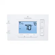
5 THERMOSTAT OVERVIEW Before you begin using your thermostat, you should be familiar with its features, display and the location/operation of the thermostat buttons and switches. THERMOSTAT BUTTONS AND SWITCHES THE DISPLAY 1. ) Fan Switch 10.) Thermostat is protecting the equipment from short cyclin...
7 THERMOSTAT SCHEDULE Energy Saving Factory Schedule This thermostat is programmed with the energy saving settings shown in the table below for all days of the week. Wake Leave Return Sleep Heating Schedule 6:00 AM - 70°F 8:00 AM - 62°F 5:00 PM - 70°F 10:00 PM - 62°F Cooling Schedule 6:00 AM - 75°F ...