Elica ECN636S3 - Manuals
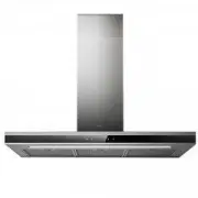
Elica ECN636S3 Range Hood – User Manual in PDF format online.
Manuals:
User Manual Elica ECN636S3


Summary
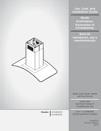
2 ENGLISH Contents Important safety notice................................................................................................................................................................................................. 3 Electrical & installation requirements ......................
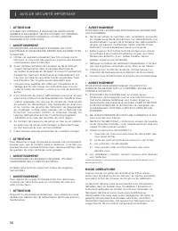
3 I IMPORTANT SAFETY NOTICE I CAUTION FOR GENERAL VENTILATING USE ONLY. DO NOT USE TO EXHAUST HAZARDOUS OR EXPLOSIVE MATERIALS OR VAPOURS. I WARNING TO REDUCE THE RISK OF FIRE, ELECTRIC SHOCK, ORINJURY TO PERSONS, OBSERVE THE FOLLOWING:A. Use this unit only in the manner intended by the manufacturer...
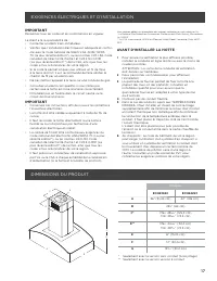
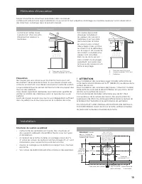
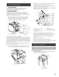
4 ELECTRICAL & INSTALLATION REQUIREMENTS IMPORTANT Observe all governing codes and ordinances. It is the customer’s responsibility: đƫ To contact a qualified electrical installer. đƫ To assure that the electrical installation is adequate and in conformance with National Electrical Code, ANSI/NFPA...
Elica Range Hoods Manuals
-
 Elica 35CC DYNAMIQUE RED/F/35
User Manual
Elica 35CC DYNAMIQUE RED/F/35
User Manual
-
 Elica 35CC EVOQUE UMBER/F/35
User Manual
Elica 35CC EVOQUE UMBER/F/35
User Manual
-
 Elica 35CC EVOQUE/F/35
User Manual
Elica 35CC EVOQUE/F/35
User Manual
-
 Elica 35CC/F/35
User Manual
Elica 35CC/F/35
User Manual
-
 Elica ACUTA IX/F/100
User Manual
Elica ACUTA IX/F/100
User Manual
-
 Elica ADAGIO BL/F/120
User Manual
Elica ADAGIO BL/F/120
User Manual
-
 Elica ADAGIO BL/F/90
User Manual
Elica ADAGIO BL/F/90
User Manual
-
 Elica ADAGIO GME BL/A/90
User Manual
Elica ADAGIO GME BL/A/90
User Manual
-
 Elica Adele BL MAT/A/60
User Manual
Elica Adele BL MAT/A/60
User Manual
-
 Elica Adele BL MAT/A/90
User Manual
Elica Adele BL MAT/A/90
User Manual
-
 Elica Adele BLIX/A/60
User Manual
Elica Adele BLIX/A/60
User Manual
-
 Elica Adele BLIX/A/90
User Manual
Elica Adele BLIX/A/90
User Manual
-
 Elica APLOMB-RS BL/A/60
User Manual
Elica APLOMB-RS BL/A/60
User Manual
-
 Elica APLOMB-RS BL/A/90
User Manual
Elica APLOMB-RS BL/A/90
User Manual
-
 Elica APLOMB-RS WH/A/60
User Manual
Elica APLOMB-RS WH/A/60
User Manual
-
 Elica APLOMB-RS WH/A/90
User Manual
Elica APLOMB-RS WH/A/90
User Manual
-
 Elica AUDREYHEAVYMETALF50
User Manual
Elica AUDREYHEAVYMETALF50
User Manual
-
 Elica BELT LUX BL/A/55
User Manual
Elica BELT LUX BL/A/55
User Manual
-
 Elica BELT LUX BL/A/80
User Manual
Elica BELT LUX BL/A/80
User Manual
-
 Elica BELT LUX WH/A/55
User Manual
Elica BELT LUX WH/A/55
User Manual