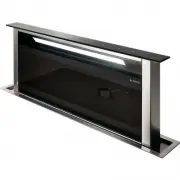
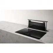
Elica EAS328SS - Manuals
Elica EAS328SS Range Hood – User Manual in PDF format online.
Manuals:
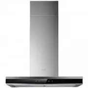
User Manual Elica EAS328SS


Summary
2 ENGLISH Contents Important safety notice ................................................................................................................................................................................................ 3List of materials ................................................
3 I WARNING TO REDUCE THE RISK OF A RANGE TOP GREASE FIRE. a) Never leave surface units unattended at high settings. Boilovers cause smoking and greasy spillovers that may ignite. Heat oils slowly on low or medium settings. b) Always turn hood ON when cooking at high heat or when flambeing food (I.e...
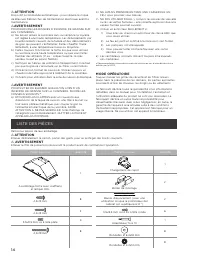
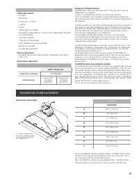
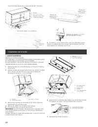
4 Parts no supplied Tools/Materials required • Level • Drill • .1” (3.0 mm) drill bit • Pencil • Pliers • Tape measure or ruler • Caulking gun and weatherproof caulking compound • Flat-blade screwdriver • Phillips screwdriver • Saber or keyhole saw • Metal snips • Vent clamps Parts needed • 6” (15.2...
Elica Range Hoods Manuals
-
 Elica 35CC DYNAMIQUE RED/F/35
User Manual
Elica 35CC DYNAMIQUE RED/F/35
User Manual
-
 Elica 35CC EVOQUE UMBER/F/35
User Manual
Elica 35CC EVOQUE UMBER/F/35
User Manual
-
 Elica 35CC EVOQUE/F/35
User Manual
Elica 35CC EVOQUE/F/35
User Manual
-
 Elica 35CC/F/35
User Manual
Elica 35CC/F/35
User Manual
-
 Elica ACUTA IX/F/100
User Manual
Elica ACUTA IX/F/100
User Manual
-
 Elica ADAGIO BL/F/120
User Manual
Elica ADAGIO BL/F/120
User Manual
-
 Elica ADAGIO BL/F/90
User Manual
Elica ADAGIO BL/F/90
User Manual
-
 Elica ADAGIO GME BL/A/90
User Manual
Elica ADAGIO GME BL/A/90
User Manual
-
 Elica Adele BL MAT/A/60
User Manual
Elica Adele BL MAT/A/60
User Manual
-
 Elica Adele BL MAT/A/90
User Manual
Elica Adele BL MAT/A/90
User Manual
-
 Elica Adele BLIX/A/60
User Manual
Elica Adele BLIX/A/60
User Manual
-
 Elica Adele BLIX/A/90
User Manual
Elica Adele BLIX/A/90
User Manual
-
 Elica APLOMB-RS BL/A/60
User Manual
Elica APLOMB-RS BL/A/60
User Manual
-
 Elica APLOMB-RS BL/A/90
User Manual
Elica APLOMB-RS BL/A/90
User Manual
-
 Elica APLOMB-RS WH/A/60
User Manual
Elica APLOMB-RS WH/A/60
User Manual
-
 Elica APLOMB-RS WH/A/90
User Manual
Elica APLOMB-RS WH/A/90
User Manual
-
 Elica AUDREYHEAVYMETALF50
User Manual
Elica AUDREYHEAVYMETALF50
User Manual
-
 Elica BELT LUX BL/A/55
User Manual
Elica BELT LUX BL/A/55
User Manual
-
 Elica BELT LUX BL/A/80
User Manual
Elica BELT LUX BL/A/80
User Manual
-
 Elica BELT LUX WH/A/55
User Manual
Elica BELT LUX WH/A/55
User Manual