DeLonghi DEGH60ST - Manuals
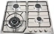
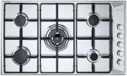
User Manual DeLonghi DEGH60ST


Summary
2 Dear Customer, Thank you for having purchased and given your preference to our product. The safety precautions and recommendations reported below are for your own safety and that of others. Theywill also provide a means by which to make full use ofthe features offered by your appliance. Please kee...
3 IMPORTANT PRECAUTIONS AND RECOMMENDATIONS FORUSE OF ELECTRICAL APPLIANCES Use of any electrical appliance implies the necessity to follow a series of fundamentalrules. In particular: ■ Never touch the appliance with wet hands or feet; ■ do not operate the appliance barefooted; ■ do not allow child...
4 470 35 min 500 550 100 580 min Figure 1 DIMENSIONS (Table 2): (Note: Also refer to Figure 1) General Dimensions Width 580 mm Depth 500 mm Depth Below Mounting Surface 30 mm Cut-out Dimensions Width 550 mm Depth 470 mm INSTALLATION CAUTION: ■ This appliance must be installed in accordance with thes...
Manual DeLonghi DEGH60ST


Summary
2 Dear Customer, Thank you for having purchased and given your preference to our product. The safety precautions and recommendations reported below are for your own safety and that of others. Theywill also provide a means by which to make full use ofthe features offered by your appliance. Please kee...
3 IMPORTANT PRECAUTIONS AND RECOMMENDATIONS FORUSE OF ELECTRICAL APPLIANCES Use of any electrical appliance implies the necessity to follow a series of fundamentalrules. In particular: ■ Never touch the appliance with wet hands or feet; ■ do not operate the appliance barefooted; ■ do not allow child...
4 470 35 min 500 550 100 580 min Figure 1 DIMENSIONS (Table 2): (Note: Also refer to Figure 1) General Dimensions Width 580 mm Depth 500 mm Depth Below Mounting Surface 30 mm Cut-out Dimensions Width 550 mm Depth 470 mm INSTALLATION CAUTION: ■ This appliance must be installed in accordance with thes...
DeLonghi Hobs Manuals
-
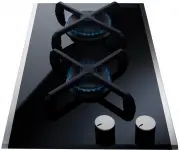 DeLonghi DE302GB
User Manual
DeLonghi DE302GB
User Manual
-
DeLonghi DE302GB
Manual
-
 DeLonghi DE302GBX1
User Manual
DeLonghi DE302GBX1
User Manual
-
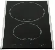 DeLonghi DE302IB
User Manual
DeLonghi DE302IB
User Manual
-
DeLonghi DE302IB
Manual
-
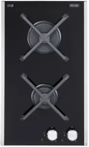
 DeLonghi DE30WGB
User Manual
DeLonghi DE30WGB
User Manual
-
DeLonghi DE30WGB
Manual
-
 DeLonghi DE30WGBX1
User Manual
DeLonghi DE30WGBX1
User Manual
-
 DeLonghi DEGH60
User Manual
DeLonghi DEGH60
User Manual
-
DeLonghi DEGH60
Manual
-
 DeLonghi DEGH60BGX1
User Manual
DeLonghi DEGH60BGX1
User Manual
-
 DeLonghi DEGH60STF
User Manual
DeLonghi DEGH60STF
User Manual
-
 DeLonghi DEGH70BGX1
User Manual
DeLonghi DEGH70BGX1
User Manual
-
 DeLonghi DEGH70W
User Manual
DeLonghi DEGH70W
User Manual
-
 DeLonghi DEGH90BGX1
User Manual
DeLonghi DEGH90BGX1
User Manual
-
 DeLonghi DEGH90STF
User Manual
DeLonghi DEGH90STF
User Manual
-
 DeLonghi DEGH90WF
User Manual
DeLonghi DEGH90WF
User Manual
-
DeLonghi DEGH90WF
Manual
-
 DeLonghi DEGHBG60
User Manual
DeLonghi DEGHBG60
User Manual
-
 DeLonghi DEGHBG90
User Manual
DeLonghi DEGHBG90
User Manual