DeLonghi DEGH90WF - User Manual
DeLonghi DEGH90WF Hob – User Manual, read for free online in PDF format. We hope this helps you resolve any issues you may have. If you have further questions, please contact us through the contact form.


Table of Contents:
- Page 2 – PRODUCT LABEL
- Page 3 – IMPORTANT PRECAUTIONS AND RECOMMENDATIONS; After use, ensure that the knobs are in off position.
- Page 4 – Figure 1; Width; INSTALLATION; appliance
- Page 5 – Figure 2; This appliance shall; not; be used as a space heater, especially if installed in marine
- Page 6 – Figure 3
- Page 7 – ing care to overlap the gasket at the corners.; Figure 4; Take care not to damage the countertop.
- Page 8 – Figure 5b; Gas connection for
- Page 10 – TABLE FOR THE CHOICE OF THE INJECTORS; Natural gas; INSTALLATION WITH A FLEXIBLE HOSE ASSEMBLY; with internal diameter of 10 mm minimum.; : After connection the installer must check that the; IMPORTANT WARNING; : The installer shall ensure the hose assembly is
- Page 11 – CONVERSION PROCEDURE; REPLACING THE INJECTORS; To replace the injectors proceed as follows:; IMPORTANT; Figure 6
- Page 12 – MINIMUM BURNER SETTING ADJUSTMENT; Normally for Universal LPG, fully tighten the adjustment screw.; LUBRICATING THE GAS TAP; Figure 8
- Page 13 – ELECTRICAL REQUIREMENTS; suitable for the power consumed by the appliance.
- Page 15 – USE and CARE
- Page 16 – CONTROL PANEL; GAS BURNERS; Fish; The electric ignition is; GAS HOB
- Page 17 – USING GAS BURNERS
- Page 18 – – Adjust the gas valve to the desired position.; Important; To re-light the burner, return the knob to the closed; wait for at; and then repeat the lighting procedure.
- Page 19 – do not use pans with concave or convex bases
- Page 20 – CORRECT USE OF TRIPLE-RING BURNER; To use the WOK, you must place the wok stand in the; CORRECT; position as; WRONG; GRILL FOR SMALL COOKWARE; used to prevent the cookware from tipping over.
- Page 21 – Note; BURNERS AND GRIDS; Cleaning and Maintenance
- Page 22 – Note: To avoid damage to the electric ignition do not use it when the
- Page 23 – CORRECT POSITIONING OF THE TRIPLE-RING BURNER; Then position the cap “
- Page 24 – CORRECT POSITIONING OF THE FISH BURNER; This burner must be correctly positioned as shown in the figure 21.
- Page 25 – SERVICE AND MAINTENANCE; Servicing the appliance:; LUBRICATION OF THE GAS TAPS
INSTALLATION and SERVICE INSTRUCTIONS
USE and CARE INSTRUCTIONS
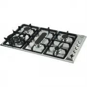
BUILT-IN GAS
HOB
Model:
DEGH90WF
distributed by
DèLonghi
Pty Ltd
"Loading the manual" means you need to wait until the file loads and becomes available for online reading. Some manuals are very large, and the time they take to appear depends on your internet speed.
Was this manual helpful?
About this manual
- Brand
- DeLonghi
- Model
- DEGH90WF
- Document type
- User Manual
- Category
- Hob
- Language(s)
- English
- Pages
- 28
- File size
- 1.3 MB
- Format
Summary
2 Dear Customer, Thank you for having purchased and given your preference to our product. The safety precautions and recommendations reported below are for your own safety and that of others. Theywill also provide a means by which to make full use ofthe features offered by your appliance. Please kee...
3 IMPORTANT PRECAUTIONS AND RECOMMENDATIONS FORUSE OF ELECTRICAL APPLIANCES Use of any electrical appliance implies the necessity to follow a series of fundamentalrules. In particular: ■ Never touch the appliance with wet hands or feet; ■ do not operate the appliance barefooted; ■ do not allow child...
4 480 70 60 60 min 0 – 2 840 200 min 0 – 2 860 100 200 500 Area forelectrical connection Area forgas connection Figure 1 DIMENSIONS: (Note: Also refer to Figure 1 above) General Dimensions Width 860 mm Depth 500 mm Depth Below Mounting Surface 30 mm Cut-out Dimensions Width 840 mm Depth 480 mm INSTA...
Ask a question
Related manuals
More DeLonghi Hobs models
Other DeLonghi appliances
 DeLonghi 14 F Manual
 DeLonghi 24 E Manual
 DeLonghi 634H Manual
 DeLonghi 3300 User Manual
 DeLonghi 5500 User Manual
 DeLonghi AC 230 User Manual
 DeLonghi AD679/699 Manual
 DeLonghi BAR 32 User Manual
 DeLonghi BC080 Manual
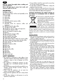 DeLonghi BCO 130 Manual
 DeLonghi BCO130 User Manual
 DeLonghi BCO264B User Manual
 DeLonghi BCO330T User Manual
 DeLonghi BCO 420 User Manual
 DeLonghi CAM51025MB User Manual
 DeLonghi CERAMIC FAN HEATER User Manual