DeLonghi Pind 30 - User Manual
DeLonghi Pind 30 Hob – User Manual, read for free online in PDF format. We hope this helps you resolve any issues you may have. If you have further questions, please contact us through the contact form.

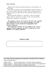
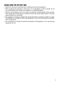
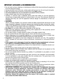
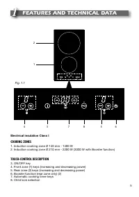
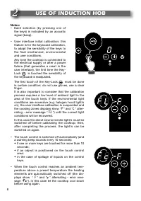
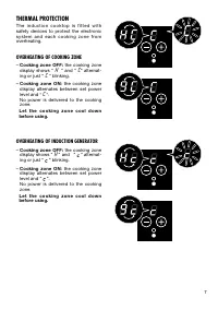
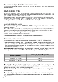

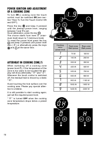
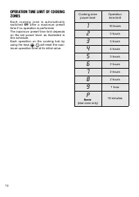
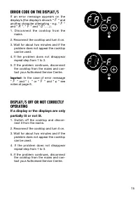
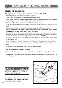

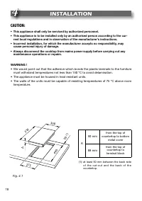
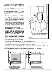
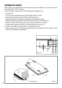
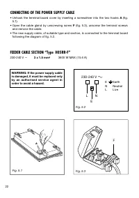

Table of Contents:
- Page 2 – PRODUCT LABEL
- Page 3 – BEFORE USING FOR THE FIRST TIME
- Page 4 – IMPORTANT SAFEGUARDS & RECOMMENDATIONS; OFF; IMPORTANT WARNING: The induction hob complies with
- Page 5 – FEATURES AND TECHNICAL DATA; Electrical insulation Class I; COOKING ZONES
- Page 6 – USE OF INDUCTION HOB; FL
- Page 7 – THERMAL PROTECTION; OVERHEATING OF COOKING ZONE; OVERHEATING OF INDUCTION GENERATOR; L e t t h e c o o k i n g z o n e c o o l d o w n
- Page 8 – INDUCTION COOKING SYSTEM; COOKWARE FOR INDUCTION COOKING; Induction Cooking Zone
- Page 9 – Switching ON; ON; Switching OFF
- Page 10 – AFTERHEAT IN COOKING ZONE/S
- Page 15 – ERROR CODE ON THE DISPLAY/S
- Page 16 – CLEANING AND MAINTENANCE; CLEANING THE CERAMIC HOB; Before you begin cleaning make sure that the hob is switched off.; Do not use harsh abrasive cleaners; SIDE STAINLESS STEEL TRIMS
- Page 18 – INSTALLATION; • This appliance shall only be serviced by authorized personnel.
- Page 19 – – I M P O R T A N T W A R N I N G ! T h i s
- Page 20 – FASTENING THE COOKTOP
- Page 21 – ELECTRICAL CONNECTION; ELECTRICAL REQUIREMENTS
- Page 22 – CONNECTING OF THE POWER SUPPLY CABLE; FEEDER CABLE SECTION “Type H05RR-F”
INSTALLATION and SERVICE INSTRUCTIONS
USE and CARE INSTRUCTIONS
distributed by
DèLonghi
Pty Ltd
DOMINO
INDUCTION HOB
model DE302IB
"Loading the manual" means you need to wait until the file loads and becomes available for online reading. Some manuals are very large, and the time they take to appear depends on your internet speed.
Was this manual helpful?
About this manual
- Brand
- DeLonghi
- Model
- Pind 30
- Document type
- User Manual
- Category
- Hob
- Language(s)
- English
- Pages
- 24
- File size
- 1.7 MB
- Format
Summary
2 Dear Customer, Thank you for having purchased and given your preference to our product. The safety precautions and recommendations reported below are for your own safety and that of others. They will also provide ameans by which to make full use of the features offered by yourappliance. Please kee...
3 BEFORE USING FOR THE FIRST TIME • Read the instructions carefully before installing and using the appliance. • After unpacking the appliance, make sure it is not damaged. In case of doubt, do not use the appliance and contact your supplier or a qualified engineer. • Remove all packaging and do not...
4 IMPORTANT SAFEGUARDS & RECOMMENDATIONS • Do not carry out any cleaning or maintenance without first disconnecting the appliance from the electrical supply. • During and after use of the hob, certain parts will become hot. Do not touch hot parts.• After use always ensure that the controls are i...
Ask a question
Related manuals
More DeLonghi Hobs models
Other DeLonghi appliances
 DeLonghi 14 F Manual
 DeLonghi 24 E Manual
 DeLonghi 634H Manual
 DeLonghi 3300 User Manual
 DeLonghi 5500 User Manual
 DeLonghi AC 230 User Manual
 DeLonghi AD679/699 Manual
 DeLonghi BAR 32 User Manual
 DeLonghi BC080 Manual
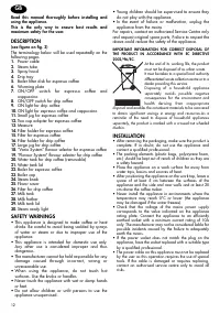 DeLonghi BCO 130 Manual
 DeLonghi BCO130 User Manual
 DeLonghi BCO264B User Manual
 DeLonghi BCO330T User Manual
 DeLonghi BCO 420 User Manual
 DeLonghi CAM51025MB User Manual
 DeLonghi CERAMIC FAN HEATER User Manual