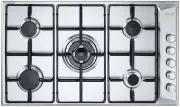
DeLonghi DEGH90STF - User Manual
DeLonghi DEGH90STF Hob – User Manual, read for free online in PDF format. We hope this helps you resolve any issues you may have. If you have further questions, please contact us through the contact form.


Table of Contents:
- Page 2 – PRODUCT LABEL; Approval Requirements for Domestic Gas cooking appliances
- Page 3 – professionally qualified technician.; This film must be removed before using the; ■ IMPORTANT: The use of suitable protective clothing/gloves is
- Page 6 – INSTALLATION; ELECTRICAL REQUIREMENTS; the load specified on the plate.
- Page 7 – established electrical regulations.; I g n i t i o n c o i l; C A; S p a r k e l e c t r o d e s; Figure 1; N L
- Page 8 – CLEARANCES; Cooktop; Figure 2b; electrical connection
- Page 9 – supplied with the appliance, as shown in the figure below.; should be fitted 100
- Page 10 – FASTENING THE INSTALLATION BRACKETS; fastening the top to fixture panels from 2 to 4 cm thick.; FASTENING THE COOKER TOP; ” out along the fixture hole, making sure that the jun
- Page 11 – GAS SUPPLY; Do not use any naked flame; Gas connection for; Figure 4a
- Page 12 – INSTALLATION WITH A FLEXIBLE HOSE ASSEMBLY; After connection the installer must check that the hose is
- Page 13 – To replace the injectors proceed as follows:
- Page 14 – surface along with the duplicate data plate.; Adjusting the minimum burner setting
- Page 15 – MINIMUM BURNER SETTING ADJUSTMENT; With the burner lit, turn the control knob to the minimum position.; Normally for ULPG fully tighten the adjustment screw.; LUBRICATING THE GAS TAP; Figure 6
- Page 16 – USE and CARE; NOT use or store flammable materials near this appliance.; DO NOT MODIFY THIS APPLIANCE.
- Page 17 – GAS BURNERS; Figure 7
- Page 18 – USING GAS BURNERS; The gas flow to the burner is controlled by a tap.; Figure 8
- Page 19 – Important; To re-light the burner, return the knob to closed “; wait for at; and then repeat the lighting procedure.
- Page 20 – COOKING HINTS FOR GAS HOBS; When deep fat frying:; SMALL PAN ADAPTER
- Page 21 – To use the WOK, you must place the wok stand in the; position as shown; MUST BE PLACED ONLY; CORRECT
- Page 22 – CLEANING and MAINTENANCE; GENERAL ADVICE; and disconnected from the electrical power supply.; ENAMELLED PARTS; Dry preferably with a soft cloth.; STAINLESS STEEL AND PAINTED OR SILK-SCREEN PRINTED SURFACES; Clean using an appropriate product. Always dry thoroughly.; irreparably damage the surface.; GAS TAPS
- Page 23 – BURNERS AND PAN SUPPORTS; The ignition plug and the probe must be very carefully cleaned.; CORRECT REPLACEMENT OF THE AUXILIARY, AND SEMI-RAPID BURNER; It is very important to check that the burner flame spreader “
- Page 24 – CORRECT REPLACEMENT OF THE TRIPLE-RING BURNER
- Page 25 – SERVICE AND MAINTENANCE; 30 or 240 VAC power supply is connected.; Servicing the appliance:
D E ’ L O N G H I
C O O K I N G
I N S TA L L AT I O N a n d S E R V I C E I N S T R U C T I O N S
U S E a n d C A R E I N S T R U C T I O N S
D E G H 9 0 S T F
G A S C O O K T O P
distributed by
DeLonghi Australia Pty Ltd
DeLonghi New Zealand Ltd
"Loading the manual" means you need to wait until the file loads and becomes available for online reading. Some manuals are very large, and the time they take to appear depends on your internet speed.
Was this manual helpful?
About this manual
- Brand
- DeLonghi
- Model
- DEGH90STF
- Document type
- User Manual
- Category
- Hob
- Language(s)
- English
- Pages
- 28
- File size
- 1.4 MB
- Format
Summary
2 PRODUCT LABEL Dear Customer, Thank you for having purchased and given your preference to our product. The safety precautions and recommendations reported below are for your own safety and that of others. They will also provide a means by which to make full use of the features offered by your appli...
3 IMPORTANT SAFETY PRECAUTIONS AND RECOMMENDATIONS IMPORTANT: This appliance is designed and manufactured solely for the cooking of domestic (household) food and is not suitable for any non domestic application and therefore should not be used in a commercial environment. The appliance guarantee wil...
6 INSTALLATION CAUTION: ■ Important: The use of suitable protective clothing/gloves is recommended when handling or cleaning of this appliance. ■ This appliance must be installed in accordance with these installation instructions, local gas fitting regulations, municipal building codes, water supply...
Ask a question
Related manuals
More DeLonghi Hobs models
Other DeLonghi appliances
 DeLonghi 14 F Manual
 DeLonghi 24 E Manual
 DeLonghi 634H Manual
 DeLonghi 3300 User Manual
 DeLonghi 5500 User Manual
 DeLonghi AC 230 User Manual
 DeLonghi AD679/699 Manual
 DeLonghi BAR 32 User Manual
 DeLonghi BC080 Manual
 DeLonghi BCO 130 Manual
 DeLonghi BCO130 User Manual
 DeLonghi BCO264B User Manual
 DeLonghi BCO330T User Manual
 DeLonghi BCO 420 User Manual
 DeLonghi CAM51025MB User Manual
 DeLonghi CERAMIC FAN HEATER User Manual