Broan-NuTone BCSEK130WW - Manuals
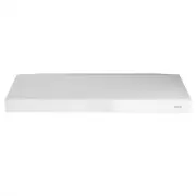
User Manual Broan-NuTone BCSEK130WW


Summary
INST ALLA TION MANUAL TABLE OF CONTENTS 2 Safety . . . . . . . . . . . . . . . . . . . . . . . . . . . . . . . . . 3-4 Operation . . . . . . . . . . . . . . . . . . . . . . . . . . . . . . . 5 Cleaning and Maintenance . . . . . . . . . . . . . . . . . 6 MotorGrease FilterNon-Ducted Recirculation Fil...
INSTALLATION MANUAL SAFETY 3 READ AND SAVE THESE INSTRUCTIONS ! Intended for domestic cooking only ! INSTALLER: LEAVE THIS MANUAL WITH HOMEOWNER. In U.S.A., register your range hood online at www.broan.com In Canada, register your range hood online at www.broan.ca ! WARNING TO REDUCE THE RISK OF FIR...
INST ALLA TION MANUAL SAFETY 4 ! WARNING TO REDUCE THE RISK OF A RANGE TOP GREASE FIRE: a) Never leave surface units unattended at high settings. Boilovers cause smoking and greasy spillovers that may ignite. Heat oils slowly on low or medium settings. b) Always turn hood ON when cooking at high hea...
Broan-NuTone Range Hoods Manuals
-
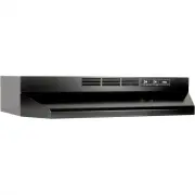 Broan-NuTone 413023
User Manual
Broan-NuTone 413023
User Manual
-
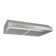
 Broan-NuTone AR130SS
User Manual
Broan-NuTone AR130SS
User Manual
-
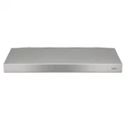
 Broan-NuTone AVSC130SS
User Manual
Broan-NuTone AVSC130SS
User Manual
-
 Broan-NuTone BCDF142SS
User Manual
Broan-NuTone BCDF142SS
User Manual
-
 Broan-NuTone BCSD136SS
User Manual
Broan-NuTone BCSD136SS
User Manual
-
 Broan-NuTone BCSQ130SS
User Manual
Broan-NuTone BCSQ130SS
User Manual
-
 Broan-NuTone BKSH130SS
User Manual
Broan-NuTone BKSH130SS
User Manual
-
 Broan-NuTone BUEZ030WW
User Manual
Broan-NuTone BUEZ030WW
User Manual
-
 Broan-NuTone BUEZ130WW
User Manual
Broan-NuTone BUEZ130WW
User Manual
-
 Broan-NuTone BUEZ230WW
User Manual
Broan-NuTone BUEZ230WW
User Manual
-
 Broan-NuTone BUEZ330WW
User Manual
Broan-NuTone BUEZ330WW
User Manual
-
 Broan-NuTone BWS2304SS
User Manual
Broan-NuTone BWS2304SS
User Manual
-
 Broan-NuTone BWT2304SSB
User Manual
Broan-NuTone BWT2304SSB
User Manual
-
 Broan-NuTone E6430SS
User Manual
Broan-NuTone E6430SS
User Manual
-
 Broan-NuTone F403023
User Manual
Broan-NuTone F403023
User Manual
-
 Broan-NuTone F403611
User Manual
Broan-NuTone F403611
User Manual
-
 Broan-NuTone RL6230WH
User Manual
Broan-NuTone RL6230WH
User Manual
-
 Broan-NuTone RL6330WH
User Manual
Broan-NuTone RL6330WH
User Manual