Asko DC7784HPW - Manuals

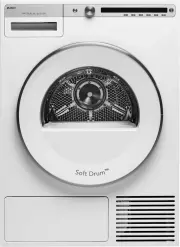
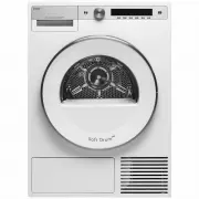
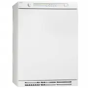
User Manual Asko DC7784HPW


Summary
3 CONTENTS THIS USER MANUAL 4 IMPORTANT SAFETY INFORMATION 5 FOR A GOOD ENVIRONMENT 6 Packaging materials 6 Management of end-of-life drying cabinet 6 DESCRIPTION OF THE DRYING CABINET 7 Air flow in the cabinet 8 CONTROL PANEL 9 Function of the button 9 Display 9 Language setting 10 PLACEMENT 11 UNP...
4 The contents of this user manual describe function , operation and optimisation of drying programmes , as well as instruc- tions for installation and maintenance . Alongside the User Manual there is a Service Manual. THIS USER MANUAL
5 IMPORTANT SAFETY INFORMATION Applicable to installation in the EU The drying cabinet can be used by children over the age of 8 and persons (including children) with various disabilities or inadequate experience and knowledge, provided they are kept under supervision or are given instructions o...
Asko Dryers Manuals
-
 Asko DC7573
User Manual
Asko DC7573
User Manual
-
 Asko DC7774
User Manual
Asko DC7774
User Manual
-
 Asko DC7774VWAU
User Manual
Asko DC7774VWAU
User Manual
-
 Asko T208C.W.AU
User Manual
Asko T208C.W.AU
User Manual
-
 Asko T208H.W
User Manual
Asko T208H.W
User Manual
-
Asko T208H.W
Manual
-
 Asko T408HD.W
User Manual
Asko T408HD.W
User Manual
-
Asko T408HD.W
Manual
-
 Asko T410HD.W
User Manual
Asko T410HD.W
User Manual
-
 Asko T608HX
User Manual
Asko T608HX
User Manual
-
 Asko T754C
User Manual
Asko T754C
User Manual
-
 Asko T754CHP
User Manual
Asko T754CHP
User Manual
-
 Asko T784C
User Manual
Asko T784C
User Manual
-
 Asko T784CHP
User Manual
Asko T784CHP
User Manual
-
 Asko T884XLCHP
User Manual
Asko T884XLCHP
User Manual
-
 Asko TDC112C G
User Manual
Asko TDC112C G
User Manual
-
 Asko T608HX.S
Manual
Asko T608HX.S
Manual
-
 Asko T411HD.W
Manual
Asko T411HD.W
Manual
-
 Asko T608HX.W
Manual
Asko T608HX.W
Manual
-
 Asko T210H.W.P
Manual
Asko T210H.W.P
Manual