Black & Decker MTE912 - User Manual

Black & Decker MTE912 Grass Trimmer – User Manual, read for free online in PDF format. We hope this helps you resolve any issues you may have. If you have further questions, please contact us through the contact form.

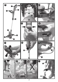


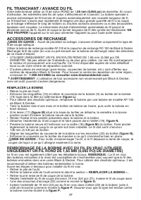


Table of Contents:
- Page 3 – SAFETY gUIDELINES - DEFINITIONS; IMPORTANT SAFETY WARNINgS AND INSTRUCTIONS; TO REDUCE RISK OF INJURY:
- Page 4 – examples of these chemicals are:; READ ALL INSTRUCTIONS; MAKE SURE that other persons and pets are at least 100 feet (30m) away.
- Page 5 – SAvE THESE INSTRUCTIONS; SYMBOLS; SAFETY WARNINgS AND INSTRUCTIONS: POLARIZED PLUgS
- Page 6 – ASSEMBLY AND ADJUSTMENT; UNPLUg THE TRIMMER BEFORE ATTEMPTINg TO ATTACH THE gUARD,; ATTACHINg THE gUARD; NEvER OPERATE TRIMMER WITHOUT gUARD FIRMLY IN PLACE.; ATTACHINg THE AUXILIARY HANDLE
- Page 7 – OPERATINg INSTRUCTIONS
- Page 8 – REPLACEMENT ACCESSORIES; REPLACINg THE SPOOL; MAINTENANCE
- Page 9 – TROUBLESHOOTINg; TRIMMER RUNS SLOWLY; Problem; SERvICE INFORMATION
- Page 10 – FULL TWO-YEAR HOME USE WARRANTY
- Page 11 – MODE D’EMPLOI
- Page 12 – RÉDUCTION DES RISQUES DE BLESSURES :; BIEN LIRE ET COMPRENDRE TOUTES LES DIRECTIvES AvANT; LIgNES DIRECTRICES EN MATIèRE DE SÉCURITÉ - DÉFINITIONS
- Page 14 – AvERTISSEMENTS DE SÉCURITÉ ET DIRECTIvES :
- Page 15 – CONFIgURATION DE L’ASSEMBLAgE ET DES RÉgLAgES; FIXATION DE LA POIgNÉE AUXILIAIRE
- Page 16 – REMARQUE; COUPE EN BORDURE
- Page 17 – REMPLACER LA BOBINE; REMBOBINAgE DE LA BOBINE AvEC DU FIL EN vRAC (UTILISER
- Page 18 – ENTRETIEN; DÉPANNAgE; L’OUTIL FONCTIONNE LENTEMENT; Problème Cause possible
- Page 20 – INFORMACION CLAvE QUE DEBE SABER:; CONSERvE ESTE MANUAL PARA FUTURAS CONSULTAS.; MANUAL DE INSTRUCCIONES; de POdAdOrA / BOrdeAdOrA
- Page 21 – ADvERTENCIAS E INSTRUCCIONES IMPORTANTES SOBRE SEgURIDAD; REDUCIR EL RIESgO DE LESIONES:; PRECAUCIÓN; estas sustancias químicas:; LEA TODAS LAS INSTRUCCIONES; PAUTAS DE SEgURIDAD/DEFINICIONES
- Page 23 – CONSERvE ESTAS INSTRUCCIONES; INSTRUCCIONES Y ADvERTENCIAS DE SEgURIDAD:; Para reducir el riesgo de descarga eléctrica, utilice
- Page 25 – FUNCIONAMIENTO; ENCENDIDO Y APAgADO
- Page 26 – CUERDA DE CORTE/ALIMENTACIÓN DE LA CUERDA; ACCESORIOS DE REPUESTO; REEMPLAZO DE CARRETES
- Page 27 – LA HERRAMIENTA FUNCIONA LENTAMENTE.
- Page 28 – MANTENIMIENTO
- Page 30 – AÑOS DE gARANTIA
- Page 33 – note: Several passes may be required with long grass.; figure f insert) under the; read all instructions; instruction manual; safetY guidelines - definitions; Please read Before returning tHis Product for anY reason.; Vea el esPanol en la contraPortada.
- Page 34 – Pautas de seguridad/definiciones; information sur les réParations
1
INSTRUCTION MANUAL
Trimmer/edger
KEY INFORMATION YOU SHOULD KNOW:
• The guard must be installed before trimming or edging - if not, the motor will overheat.
• When replacing the line, use only .065 inch diameter ROUND line (B&D Model #AF-100 is
recommended) - otherwise the trimmer will not function properly.
• Do not bump the feed head against the ground - it will disrupt the automatic feed mechanism.
• Always use the cord retention feature
Thank you for choosing Black & Decker! To register your new product go to
www.BlackandDecker.com/NewOwner
PLEASE READ BEFORE RETURNINg THIS PRODUCT FOR ANY REASON.
If you have a question or experience a problem with your Black & Decker purchase, go to
http://www.blackanddecker.com/instantanswers
If you can’t find the answer or do not have access to the Internet,
call 1-800-544-6986 from 8 a.m. to 5 p.m. EST Mon. - Fri. to speak with an agent.
Please have the catalog number available when you call.
SAvE THIS MANUAL FOR FUTURE REFERENCE.
vEA EL ESPANOL EN LA CONTRAPORTADA.
INSTRUCTIVO DE OPERACIÓN, CENTROS DE SERVICIO Y PÓLIZA DE GARANTÍA.
ADvERTENCIA: LÉASE ESTE INSTRUCTIVO ANTES DE USAR EL PRODUCTO.
CATALOg NUMBERS
gH900, gH912
"Loading the manual" means you need to wait until the file loads and becomes available for online reading. Some manuals are very large, and the time they take to appear depends on your internet speed.
Summary
3 SAFETY gUIDELINES - DEFINITIONS It is important for you to read and understand this manual. The information it contains relates to protecting YOUR SAFETY and PREvENTINg PROBLEMS. The symbols below are used to help you recognize this information. DANgER: Indicates an imminently hazardous situation ...
4 CAUTION: Failure to comply with the recommendations outlined in the key information section will void warranty. WARNINg: Some dust created by this product contains chemicals known to the State of California to cause cancer, birth defects or other reproductive harm. Some examples of these chemicals...
5 • DON’T ABUSE CORD – Never carry trimmer by cord or yank it to disconnect from receptacle. Keep cord from heat, oil, and sharp edges. • REPLACEMENT PARTS – When servicing use only identical replacement parts. • MAINTAIN TRIMMERS WITH CARE – Follow instructions in maintenance section. Keep handles ...