Page 3 - Contents
818 20 68-00/0 3 Contents Important Safety Instructions . . . . . . . . . . . . . . . . . . . . . . . . . . . . . . . . . . . . 5 Environmental Information . . . . . . . . . . . . . . . . . . . . . . . . . . . . . . . . . . . . . . 7 Packaging . . . . . . . . . . . . . . . . . . . . . . . . . . . . ...
Page 5 - Important Safety Instructions
818 20 68-00/0 5 1 Important Safety Instructions These warnings are provided in the interests of your safety. Ensure that you understand them all before installing or using this appliance. Your safety is of paramount importance. If you are unsure about any of the meanings of these warnings contact t...
Page 7 - Environmental Information; Packaging; Appliance Transport
818 20 68-00/0 7 Environmental Information Packaging All transit packaging materials are environmentally compatible and can be reused. Wood is un-treated. The plastics can be recycled and are identified as follows:>PE< for polyethylene, e.g. the outer covering and the bags in the interior.>...
Page 8 - Before Use
8 818 20 68-00/0 Before Use Packaging 0 1. Remove all adhesive tape and packaging from the interior of the appli-ance. 3 Any remnants of adhesive can be removed with white spirit. 2. Remove the transport protection pieces and pull off the adhesive tape. 3. Wash the inside of the appliance with lukew...
Page 9 - Fitting the Door Handles
818 20 68-00/0 9 Fitting the Door Handles 1 Caution! Do not use excessive force and overtighten the screws (max. 2 Nm) as you may damage the door handles. 0 1. Screw the top handle bracket to the handle rod (1). Fit the bottom han-dle bracket on the lower left-hand side of the door (2). 2. Fit the t...
Page 10 - Installation; Installation Location
10 818 20 68-00/0 Installation Installation Location The appliance should be installed in a well ventilated, dry room. Energy use is affected by the ambient temperature. The appliance should therefore– not be exposed to direct sunlight;– not be installed next to radiators, cookers or other sources o...
Page 11 - The Refrigerator needs Ventilation; Appliance Alignment
Installation 818 20 68-00/0 11 The Refrigerator needs Ventilation Air is fed under the door through the vent slots in the base and is exhausted upwards along the back wall. To ensure proper air circulation never cover or alter the vent openings. Important! If the appliance is installed under a hangi...
Page 12 - Electrical Connection
Installation 12 818 20 68-00/0 Electrical Connection Any electrical work required to install this appliance should be carried out by a qualified electrician or competent person. 1 WARNING – THIS APPLIANCE MUST BE EARTHED The manufacturer declines any liability should these safety measures not be obs...
Page 13 - Installation of the carbon filter; Reversing the Door
818 20 68-00/0 13 Installation of the carbon filter On delivery the carbon filter is placed in a plastic bag to ensure the length of life of the carbon filter. The filter should be placed behind the grill before the cabinet is turned on. 0 1. The cover can be opened by simultane-ously pressing the l...
Page 16 - Description of the Appliance; View of the appliance
16 818 20 68-00/0 Description of the Appliance View of the appliance ➀ Control panel ➁ Butter and cheese compartment with lid ➂ Door storage compartments ➃ Variable storage box ➄ Bottle compartment ➅ Salad bin ➆ Shelves ➇ Quick chill shelf ➈ Filter housing ➉ Bottle and can holder ë Bottle rack í Rat...
Page 17 - Control Panel
Description of the Appliance 818 20 68-00/0 17 Control Panel 1 ON/OFF button 2 Temperature display 3 Buttons for adjusting the temperature 4 FAST CHILL button and FAST CHILL indicator light (yellow) • FAST CHILL for intensive cooling in the refrigerator 5 WARNING OFF button Buttons for Adjusting the...
Page 18 - Temperature Display; Prior to Initial Start–Up
18 818 20 68-00/0 Temperature Display The temperature display can indicate several pieces of information. • During normal operation, the temperature currently present in the refrigerator (ACTUAL temperature) is displayed. • When the temperature is being adjusted a flashing display indicates the frid...
Page 19 - Temperature Adjustment
818 20 68-00/0 19 Initial Start-Up 0 1. Insert plug into mains socket. 2. Press ON/OFF button. 3. Set the refrigerator to the desired temperature (see section: "Tempera-ture Adjustment"). Temperature Adjustment With the buttons for temperature adjustment the desired temperatures in the refri...
Page 20 - FAST CHILL; FAST CHILL button
20 818 20 68-00/0 FAST CHILL FAST CHILL button The FAST CHILL function is suited for quick cooling of large quantities of goods in the refrigerator, e.g. drinks and salads for a party. 0 1. The FAST CHILL function is switched on by pressing the FAST CHILL but-ton. The yellow light illuminates.The FA...
Page 22 - Holiday Mode; Opening the Door
22 818 20 68-00/0 Holiday Mode In the holiday mode the temperature for the refrigerator is approxi-mately +15 °C. In the holiday mode it is therefore possible to leave the door of the empty refrigerator closed during periods of extended absence. Advantage: Unintentional closing of the door, or accid...
Page 23 - Interior Fittings; Storage Shelves
818 20 68-00/0 23 Interior Fittings Storage Shelves The shelf in the lowest runners over the fruit and vegetable drawer must always remain in this position, so that fruit and vegetables stay fresher for longer.The remaining storage shelves can be adjusted to various heights: 0 1. Pull the storage sh...
Page 24 - Bottle Rack; Quick Chill Shelf
Interior Fittings 24 818 20 68-00/0 Bottle Rack Place bottles in the rack with the bottleneck to the front. Important: Only store unopened bottles horizontally. The bottle rack can be tilted for storing opened bottles. 0 1. To do this pull the bottle rack for-ward until it can be tilted upwards, the...
Page 25 - Dismantling of the Bottle and Can Holder
Interior Fittings 818 20 68-00/0 25 The bottle support can be pulled out when chilling larger bottles. Dismantling of the Bottle and Can Holder 0 1. Take out the quick chill shelf with holder from the cabinet. 2. To loosen the holder from the shelf, bend the hooks/brackets that surround the backside...
Page 26 - Proper Storage
26 818 20 68-00/0 Proper Storage The cooling fan ensures an even tem-perature distribution in the fridge. There is a max. temperature differ-ence of 1 °C. Foods with different lengths of storage time can therefore be arranged on the shelves as you like, without having to take into account the differ...
Page 27 - Hints and Tips; Normal Operating Sounds
818 20 68-00/0 27 Hints and Tips Normal Operating Sounds • You may hear faint gurgling or bubbling sounds when the refrigerant is pumped through the coils or tubing at the rear, to the cooling plate/evaporator. • When the compressor is on, the refrigerant is being pumped round and you will hear a wh...
Page 28 - Defrosting; Maintenance and Cleaning; Internal Cleaning; External Cleaning
28 818 20 68-00/0 Defrosting The Fridge defrosts automatically Maintenance and Cleaning Before any maintenance or cleaning work is carried out DISCONNECT the appliance from the ELECTRICITY supply. Internal Cleaning 0 1. Clean the inside and accessories with warm water and bicarbonate of soda (5 ml t...
Page 29 - Changing the carbon filter
Maintenance and Cleaning 818 20 68-00/0 29 Changing the carbon filter To maintain the best performance the carbon filter should be chan-ged once a year with normal usage. New carbon filters can be purcha-sed from your local Service Force Centre. 0 1. The filter is placed behind the grill and can be ...
Page 30 - Replacing the Light Bulb
Maintenance and Cleaning 30 818 20 68-00/0 Replacing the Light Bulb 1 Warning! Danger of electrical shock! Before replacing the light bulb switch appliance off and remove the mains plug. Light bulb specifications: 220-240 V, max. 25 W, fitting: E 14 Important! When replacing the lamp only fit a lamp...
Page 32 - Guidelines
32 818 20 68-00/0 If after the above checks there is still a fault, call your local AEG Service Force Centre. In-guarantee customers should ensure that the above checks have been made as the engineer will make a charge if the fault is not a mechanical or electrical breakdown. Please note that proof ...
Page 33 - Technical Terminology
818 20 68-00/0 33 Technical Terminology • Refrigerant Liquids that can be used to a generate a cooling effect are known as refrigerants. They have a relatively low boiling-point, indeed so low, that the warmth from the food stored in the fridge or freezer can cause the refrigerant to boil and vapori...
Page 34 - Guarantee Conditions
34 818 20 68-00/0 Guarantee Conditions AEG offer the following guarantee to the first purchaser of this appliance. 1. The guarantee is valid for 12 months commencing when the appliance is handed over to the first retail purchaser, which must be verified by purchase invoice or similar docu-mentation....
Page 35 - Service & Spare Parts
818 20 68-00/0 35 Service & Spare Parts In the event of your appliance requiring service, or if you wish to pur-chase spare parts, please contact Service Force by telephoning: 08705 929 929 Your telephone call will be automatically routed to the Service Force Centre covering your post code area....


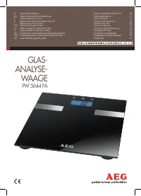 AEG PW 5644 FA User Manual
 AEG RCB53324MX User Manual
 AEG RMB56111NX User Manual
 AEG RMB76121NX User Manual
 AEG RMB96716CX User Manual
 AEG RTB91431AW User Manual
 AEG S3888-8KG User Manual
 AEG S4285-7DTI User Manual
 AEG S4288-7DR User Manual
 AEG S40070KA User Manual
 AEG S52700DSW1 User Manual
 AEG S53420CTW2 User Manual