Page 2 - Instructions; General safety instructions
Instructions 4 1 Instructions 1.1 General safety instructions Risk of personal injury • During use the appliance and its accessible parts become very hot. Never touch the heating elements during use. • Never try to put out a fire or flames with water: turn off the appliance and smother the flames wi...
Page 3 - Risk of damaging the appliance
Instructions 5 EN • Switch the appliance off immediately after use. • DO NOT MODIFY THIS APPLIANCE. • Before carrying out any work on the appliance (installation, maintenance, positioning or moving), wear personal protective equipment. • Before carrying out any work on the appliance, disconnect the ...
Page 4 - Installation
Instructions 6 • Do not use cleaning products containing chlorine, ammonia or bleach on steel parts or parts with metallic surface finishes (e.g. anodizing, nickel- or chromium-plating). • Do not wash the removable components such as the cooktop pan stands, flame-spreader crowns and burner caps in a...
Page 5 - For this appliance
Instructions 7 EN • The settings for this domestic appliance are shown on the gas setting label. • This domestic appliance is not connected to a device for extracting combustion products. It must be installed and connected in accordance with current installation regulations. Pay particular attention...
Page 6 - Identification plate
Instructions 8 1.4 Disposal This appliance must be disposed of separately from other waste (Directives 2002/95/EC, 2002/96/EC, 2003/108/EC). The appliance does not contain substances in quantities sufficient to be considered hazardous to health and the environment, in accordance with current Europea...
Page 7 - How to read the user manual
Instructions 9 EN 1.7 How to read the user manual This user manual uses the following reading conventions: 1. Sequence of instructions for use.• Standalone instruction. Instructions General information on this user manual, on safety and final disposal. Description Description of the appliance and it...
Page 8 - Description; General Description; AUX; 0 cm central UR
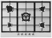
Description 10 2 Description 2.1 General Description 60 cm 70 cm side UR 1. Control panel 2. Auxiliary burner ( AUX ) 3. Semi-rapid burner ( SR ) 4. Rapid burner reduced ( RR ) 5. Ultra-rapid triple crown burner ( UR *) 6. Ultra-rapid triple crown burner ( UR ) 70 cm central UR 7. Ultra-rapid burner...
Page 9 - Cooking zones
Description 11 EN 2.2 Symbols Cooking zones Front left Centre left Rear left Central Rear right Central right Front right Internal lateral External lateral Burner knobs For lighting and adjusting the burners. Press and turn the knobs anti-clockwise to in order to light the relative burners. Turn the...
Page 10 - Use; Escaping gas may cause an explosion.
Use 12 3 Use 3.1 Instructions Escaping gas may cause an explosion. If you smell gas or notice any faults in the gas installation:• Immediately shut off the gas supply or close the gas cylinder valve. • Immediately extinguish all naked flames and cigarettes. • Do not use any light or appliance switch...
Page 11 - Remove any protective film from the; Using the cooktop; and wait 60 seconds before trying
Use 13 EN • Burners not igniting properly.• Burners failing to remain alight.• Burners extinguishing whilst in operation.• Gas valves with are difficult to turn.In case the appliance fails to operate correctly, contact the Authorised Assistance Centre in your area. 3.2 First use 1. Remove any protec...
Page 12 - Correct positioning of the grids
Use 14 Correct positioning of the grids To install the grids follow the instructions and the following figures.1. Lay the lateral grids on the cooktop paying attention to position the front teeth facing the knobs. 2. Lay the centre grid engaging the notches in the teeth of the lateral grids. In addi...
Page 13 - Practical tips for using the cooktop
Use 15 EN Practical tips for using the cooktop For better burner efficiency and to minimise gas consumption, use pans with lids and of suitable size for the burner, so that the flames do not reach up the sides of the pan. Once the contents come to the boil, turn down the flame far enough to ensure t...
Page 14 - Cleaning and maintenance; Cleaning the appliance; Ordinary daily cleaning
Cleaning and maintenance 16 4 Cleaning and maintenance 4.1 Instructions 4.2 Cleaning the appliance To keep the surfaces in good condition, they should be cleaned regularly after use. Let them cool first. Ordinary daily cleaning Always use specific products only that do not contain abrasives or chlor...
Page 15 - Cooktop grids
Cleaning and maintenance 17 EN Cooktop grids Remove the grids and clean them in lukewarm water and non-abrasive detergent. Make sure to remove any encrustations. Dry them thoroughly and return them to the cooktop. Igniters and thermocouples For correct operation the igniters and thermocouples must a...
Page 16 - Installation; Clearances above and around domestic appliances; Requirements
Installation 18 5 Installation 5.1 Clearances above and around domestic appliances This appliance must be installed by an authorised person in accordance with this instruction manual, AS/NZS 5601.1 – Gas installations (installation and pipe sizing), local gas fitting regulations, local electrical re...
Page 17 - Additional requirements for; Safety instructions; Risk of fire
Installation 19 EN 3. Additional requirements for Freestanding and Elevated Cooking Appliaces – (Measurements D & E) Where D, the distance from the periphery of the nearest burner to a horizontal combustible surface is less than 200 mm, then E shall be 10 mm or more, or the horizontal surface sh...
Page 18 - Section cut from the work surface; : 70 cm models with side UR
Installation 20 5.3 Section cut from the work surface Create an opening with the dimensions shown in the figure in the work surface of the piece of furniture. C : 70 cm models with central UR. L : 70 cm models with side UR *If there is a piece of furniture above the cooktop. In case of hood, refer t...
Page 19 - 0 cm models with side UR:
Installation 21 EN 70 cm models with side UR: G Gas connection E Electrical connection View from the bottom Rear view Right view 70 cm models with central UR: View from the bottom G Gas connection E Electrical connection Rear view Right view
Page 20 - Over built-in oven unit; Over empty kitchen unit or drawers; opens on bottom
Installation 22 5.4 Mounting Over built-in oven unit The clearance between the cooktop and the kitchen furniture or other installed appliances must be enough to ensure sufficient ventilation and air discharge.If installed above an oven, a space must be left between the bottom of the cooktop and the ...
Page 21 - Cooktop seal; Fixing using brackets; 0 cm models with central UR
Installation 23 EN Cooktop seal To prevent leakage of liquid between the frame of the cooktop and the work surface, put the insulating seal provided in position before assembly.1. Apply the seal provided along the outer edge of the appliance surface. 2. Lay the appliance in the hole on the work top ...
Page 22 - 0 cm models with lateral UR; General information
Installation 24 70 cm models with lateral UR Screw the fixing brackets ( A ) into the holes on the sides of the bottom casing to properly fasten the cooktop to the structure. 5.6 Gas connection General information This appliance is suitable for installation with Natural Gas or ULPG (propane/butane)....
Page 23 - The regulator must be fitted to the 1⁄2
Installation 25 EN Connection of the appliance to the gas supply must be in accordance with the requirements of AS5601. A ½” BSP connector at the inlet is recommended and the gas supply line to the appliance must be of adequate length to allow sufficient withdrawal of appliance for service or discon...
Page 24 - Connection to liquid gas
Installation 26 Connection to liquid gas Use a pressure regulator and make the connection on the gas cylinder following the guidelines set out in the regulations in force.Make sure that the supply pressure complies with the values indicated in the paragraph ““Burner and nozzle specifications tables”...
Page 25 - Adaptation to different types of; Removing the hob top
Installation 27 EN Air Combustion products Extractor fan 5.7 Adaptation to different types of gas If other types of gas are to be used, the nozzles must be replaced and the primary air must be adjusted. In order to replace the nozzles and adjust the burners, the hob top must be removed. Removing the...
Page 26 - Only for models with lateral UR:
Installation 28 6. Only for models with lateral UR: pull out the bracket. 7. Only for models with lateral UR : put the appliance back in normal position. 8. For each burner, unscrew the three screws that fix the burner plates to the hob top. 9. Remove the seals from the plugs and thermocouples of ea...
Page 27 - Primary air adjustment
Installation 29 EN 3. Lift the trigger of the microswitch for the gas tap ( 1 ) then remove it ( 2 ). 4. Use a 7-mm spanner to remove the nozzle and replace it with the new one for the required gas supply, following the indications given in the relevant tables (see Burner and nozzle specifications t...
Page 28 - Adjusting the minimum setting for LPG
Installation 30 Adjusting the minimum setting for natural gas Light the burner and turn it to the minimum position. Extract the gas tap knob and turn the adjustment screw next to the tap rod (depending on the model) until the correct minimum flame is achieved.Refit the knob and verify that the burne...
Page 29 - Burner and nozzle specifications tables; Electrical connection; Power voltage
Installation 31 EN Burner and nozzle specifications tables The nozzles not provided are available at Authorised Service Centres. 5.8 Electrical connection General information Check the grid characteristics against the data indicated on the plate.The identification plate bearing the technical data, s...
Page 30 - Fixed connection; Instructions for the installer; DO NOT
Installation 32 Fixed connection Fit the power line with an omnipolar circuit breaker in compliance with installation regulations.The circuit breaker should be located near the appliance and in an easily reachable position. Connection with plug and socket Make sure that the plug and socket are of th...