Page 2 - TABLE OF CONTENTS; INTRODUCTION; WARNING; Read and understand all provided literature before use.
2 TABLE OF CONTENTS Introduction ................................................................ 2 Safety ......................................................................... 3 - Manual Safety Symbols and Importan Information ......................................... 3 - International Symbols ...
Page 3 - CIRCLE AND SLASH SYMBOL; CAUTION
3 SAFETY Manual Safety Symbols And Important Information Throughout this manual and on the product itself, you will find safety alerts and helpful, informational messages preceded by symbols or key words. The following is an explanation of those symbols and key words and what they mean to you. Inter...
Page 5 - DANGER
5 Read the Manuals • Provide all users of this equipment with the Operator’s Manual for instructions on Safe Operation . Clear the Work Area • Spectators and fellow workers must be warned, and children and animals prevented from coming nearer than 15 m (50 ft.) while the unit is in use. • Take wind ...
Page 6 - PRODUCT EMISSION DURABILITY (EMISSION COMPLIANCE PERIOD); CARB And EPA Emissions Control Information; Equipment
6 WARNING Use only approved attachments. Serious injury may result from the use of a non-approved attachment combination. ECHO, INC. will not be responsible for the failure of cutting devices, attachments or accessories which have not been tested and approved by ECHO. Read and comply with all safety...
Page 7 - DESCRIPTION; ipsum
7 DESCRIPTION Locate these safety decals on your unit. Make sure the decals are legible and that you understand and follow the instructions on them. If a decal cannot be read, a new one can be ordered from your dealer. The safety decal is for example only. Your label may appear slightly different. 6...
Page 8 - CONTENTS
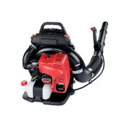
8 DESCRIPTION 1. Air Cleaner 2. Spark Plug 3. Safety Decal 4. Spark Arrestor Muffler or Spark Arrstor Muffler with Catalyst 5. Recoil Starter Handle 6. Choke 7. Purge Bulb 8. Fuel Tank 9. Fuel Tank Cap 10. Blower Pipes 11. Throttle Position Lever 12. Stop Switch 13. Shoulder Harness 14. Handle 15. T...
Page 9 - ASSEMBLY; Install Blower Pipes; NOTE; NOTE
9 ASSEMBLY WARNING Never perform maintenance or assembly procedures with engine running or serious personal injury may result. Install Blower Pipes 1. Assemble clamps (A) and (G) onto both ends of flexible pipe (B). 2. Assemble flexible pipe to elbow (D) on blower. Position clamp with cable guide lo...
Page 10 - OPERATION; laws or regulations regarding fire prevention requirements.; Always be alert for changes in operation of unit.; Fuel; Fuel Requirements; directed away from your face and body.
10 OPERATION WARNING Operation of this equipment may create sparks that can start fires around dry vegetation. This unit is equipped with a spark arrestor to prevent discharge of hot particles from the engine. Contact local fire authorities for laws or regulations regarding fire prevention requireme...
Page 11 - Handling Fuel; • Use an approved fuel container.; NOTICE
11 Handling Fuel DANGER Fuel is VERY flammable. Use extreme care when mixing, storing or handling or serious personal injury may result. • Use an approved fuel container. • DO NOT smoke near fuel. • DO NOT allow flames or sparks near fuel. • Fuel tanks/cans may be under pressure. Always loosen fuel ...
Page 12 - tainers to reduce fuel spillage.
12 B A Filling the Fuel Tank CAUTION! Slowly remove the fuel cap after stopping the engine. 1. Place the unit on a level surface.2. Clear any dirt or other debris from around the fuel filler cap. 3. Remove the fuel cap (A), and fill the fuel tank with clean, fresh fuel. Do not fill above bottom of f...
Page 13 - Starting Cold Engine; Starting Warm Engine
13 Starting Cold Engine Recoil starter: Use short pulls; only 1/2-2/3 of rope length for starting. Do not allow the rope to snap back in. Always hold the unit firmly. 1. Move throttle lever (A) forward to idle position. 2. Slide stop switch (B) forward to run position.3. Move choke (C) up to "Co...
Page 14 - Operating Blower; Stopping Engine
14 Read the Safety Section carefully. 1. Use only during appropriate hours.2. Allow the engine to warm up at a fast idle for a few minutes.3. Control engine speed with throttle trigger (C), or throttle position le- ver (A). Rotate throttle position lever forward for lower speed, back for higher spee...
Page 15 - MAINTENANCE; Skill Levels; Maintenance Intervals
15 WARNING Moving parts can amputate fingers or cause severe injuries. Keep hands, clothing and loose objects away from all openings. Always stop engine, disconnect spark plug, and make sure all moving parts have come to a complete stop before removing obstructions, clearing debris, or servicing uni...
Page 16 - aIr; IMPORTANT; Air Filter
16 15 Eng lish aIr fIlTer Level 1. Tools required: 25 - 50mm (1 - 2 in.) cleaning brush NOTE Always brush dirt and debris away from air cleaner area prior to cleaning air filter. Brush dirt off air cleaner area. Keep dirt away from engine and air intake grid. Remove air filter cover. Brush dirt from...
Page 17 - Fuel Filter; fuel; Level; DANGer; VERY; spArk; Spark Plug
17 Fuel Filter Level 1. Parts Required: Tune up kit 1. Use a clean rag to remove loose dirt from around fuel cap and empty fuel tank. 2. Pull the fuel filter from the tank. 3. Remove the filter from the line and install the new filter. DANGER Fuel is VERY flammable. Use extreme care when mixing, sto...
Page 18 - Cooling System; CoolInG; Cleaning Grill
18 Cooling System Level 2. Overheating and engine seizure can occur when: • Air intakes are blocked, preventing cooling air from reaching the cylinder. • Dust and grass build up on the outside of the cylinder. This build up insulates the engine and prevents the heat from leaving. Removal of cooling ...
Page 19 - Exhaust System; Spark Arrestor Screen; WaRNING; Do not perform maintenance on engine or muffler until engine; Cylinder Exhaust Port
19 Exhaust System Spark Arrestor Screen Level 2. Parts Required: Spark arrestor screen, Gaskets 1. Remove spark plug lead from spark plug, and remove engine cover.2. Remove spark arrestor covers (A), gaskets (B), and spark arrestor screen (C) from muffler. Replace screen if plugged with carbon depos...
Page 20 - Carburetor Adjustment; High Altitude Operation; Exhaust Port Cleaning
20 IMPORTANT Never use a metal tool to scrape carbon from the exhaust port. Do not scratch the cylinder or piston when cleaning the ex- haust port. Do not allow carbon particles to enter the cylinder. Carburetor Adjustment Engine Break-In New engines must be operated a minimum duration of two tanks ...
Page 21 - High Altitude Adjustment; Before Adjustment
21 NOTE Every unit is run at the factory and the carburetor is set in compliance with emission regulations. Carburetor adjustments, other than idle speed, must be performed by an authorized dealer. Level 2. Parts required: None. Before Adjustment Check that: • Air filter is clean and properly instal...
Page 22 - TROUBLE SHOOTING
22 TROUBLE SHOOTING 20 DANGER Fuel vapors are extremely flammable and may cause fire and/or explosion. Never test for ignition spark by grounding spark plug near cylinder plug hole, otherwise serious personal injury may result. T R A H C G N I T O O H S E L B U O R T m e l b o r k P c e h s C u t a ...
Page 23 - STORAGE
23 DANGER Do not store in enclosure where fuel fumes may accumulate or reach an open flame or spark. WARNING During operation the muffler or catalytic muffler and surrounding cover become hot. Always keep exhaust area clear of flammable debris during transportation or when storing, otherwise serious...
Page 24 - SPECIFICATIONS; MODEL ���������������������������������������������������� EB633RT
24 SPECIFICATIONS MODEL ���������������������������������������������������� EB633RT Length ------------------------------------------------------ 375 mm (14.8 in.) Width -------------------------------------------------------- 485 mm (19.0 in.)Height ------------------------------------------------...
Page 25 - WARRANTY STATEMENTS
25 WARRANTY STATEMENTS ECHO INCORPORATED LIMITED WARRANTY STATEMENT FOR ECHO AND SHINDAIWA PRODUCTS SOLD IN USA AND CANADA BEGINNING 01/01/2010 ECHO INCORPORATED'S RESPONSIBILITY ECHO Incorporated’s (ECHO, Inc.) Limited Warranty, provides to the original purchaser that this ECHO or Shindaiwa product...
Page 27 - Thank you for choosing Shindaiwa Power Equipment; PRODUCT REGISTRATION
27 Thank you for choosing Shindaiwa Power Equipment Please go to http://www.shindaiwa-usa.com to register your new product on-line. It's FAST and EASY! NOTE: your information will never be sold or misused by ECHO, Inc. Registering your purchase enables us to contact you in the unlikely event of a se...
Page 28 - SERVICING INFORMATION; them in the space provided below.; Service; and serial number of your unit.; Product Registration; and ECHO if we find it necessary to contact you.; Additional Literature
28 SERVICING INFORMATION Parts/Serial Number Genuine SHINDAIWA Parts and Assemblies for your SHINDAIWA products are available only from an Authorized SHINDAIWA Dealer. When you do need to buy parts always have the Model Number and Serial Number of the unit with you. You can find these numbers on the...
Page 29 - notes