Page 2 - Index; INSTALLATION INSTRUCTIONS; Locking and Unlocking / Changing Programming Code /
Index INSTALLATION INSTRUCTIONS Package Contents / Tools Required...........................................................Page 1 Prepare Door and Jamb...............................................................................Page 2 Adjusting Latch / Installing Latch...............................
Page 3 - Package Contents; Tools Required for Installation
Page 1 INSTALLATION INSTRUCTIONS Package Contents Tools Required Tools Required for Installation on Pre-drilled Doors: • Phillips Screwdriver Tools Required for Installation on Doors That Require Drilling: • Drill • Tape Measure • Pencil • 2-1/8” (54mm) Drill Hole Saw • 1” (25mm) Drill • 1/16” (2mm)...
Page 4 - MARK AND DRILL DOOR JAMB; PREPARE DOOR AND JAMB; For Drive in Latch, drill hole size indicated on template and press
Page 2 NOTE: For installation on doors with pre-drilled holes skip to 4e.1. TEMPLATE a. Cut out template printed on page 15 of this Manual (Figure 1a). b. Fold template and place on door 36” (915mm) from the ground as marked (Figure 1b).2. MARK THE DOOR FOR DRILLING b. Mark center hole on door edge ...
Page 5 - ADJUSTING LATCH; PULL; NOTE: Curved part of Latch always faces; INSTALLING LATCH
Page 3 5. INSTALLING THE LATCH (need phillips head screwdriver) a. Make sure the face plate sits flush with the door. Do not force the latch into the mortise flush. Chisel out excess material if necessary for a flush fit (Figure 5a). b. Using two 3/4” (19mm). screws provided, screw the latch into th...
Page 6 - INSTALLING EXTERIOR ASSEMBLY
Page 4 NOTE: Tailpiece must be positioned vertically INSTALLING EXTERIOR ASSEMBLY 7. SECURING THE EXTERIOR ASSEMBLY TO THE DOOR a. From the side marked “This side against door”, route the Control Wire through the rectangular slot in the Mounting Plate (Figure 7a). b. Place Mounting Plate against doo...
Page 7 - INSTALLING INTERIOR ASSEMBLY; ATTACH THE CONTROL WIRE TO THE INTERIOR ASSEMBLY; NOTE: Lock and unlock using Interior Knob to see if the
Page 5 INSTALLING INTERIOR ASSEMBLY 9. ATTACH THE CONTROL WIRE TO THE INTERIOR ASSEMBLY a. Use care to attach the Control Wire male plug to the Interior Assembly female socket connector (Figure 9a). b. Do not force the Control Wire male plug into the Interior Assembly female socket connector (Figure...
Page 8 - Installing Batteries; With the Door Open; NOTE: Do not touch the Keypad until the blue light turns off.; INSTALLATION OVERVIEW
Page 6 11. Installing Batteries a. Insert 4 AA high quality Alkaline batteries into the Battery Compartment in the direction noted +/- on the Compartment. The Lock will beep 2 times, the keypad will illuminate blue, and the Honeywell button will flash green twice to signify that it has received powe...
Page 9 - OPERATION INSTRUCTIONS; Exterior Assembly Overview; Indicator light; Lock button; Factory Settings
Page 7 OPERATION INSTRUCTIONS Exterior Assembly Overview Indicator light Green • Indicates Successful Programming Step • Indicates Unlocking is Successful Red • Indicates Failed Programming Step • Indicates Locking is Successful Electronic lock requires (4) High Quality AA Alkaline batteries. When a...
Page 10 - new Re-enter
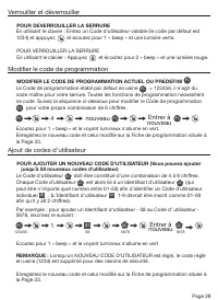
Page 8 TO UNLOCK THE LOCK Using Keypad: Enter a valid User Code (default code is 1234) and press and hear 1 beep and lights green. TO LOCK THE LOCK Using Keypad: Press and then hear 2 beeps and lights red. CHANGE CURRENT OR PRESET PROGRAMING CODE Factory default Programming Code = 123456, this is th...
Page 11 - DELETE ONE EXISTING OR PRESET USER CODE; The unit comes with a factory User ID = 01 for User Code = 1234.; SET OR CANCEL AUTO LOCK; Hear 1 beep and Light Indicator illuminates green.; position, wait more than 2 seconds or press the
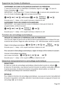
Page 9 DELETE ONE EXISTING OR PRESET USER CODE The unit comes with a factory User ID = 01 for User Code = 1234. IMPORTANT: To delete 1 User Code , the lock must have more than 1 User Code in its database. SET OR CANCEL AUTO LOCK You can set the lock to automatically close after each time the lock is...
Page 12 - , the system will remain in Vacation Mode.; and the light indicator will turn green.; Hear 1 beep and Light Indicator illuminates green then lock door
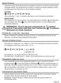
Page 10 NOTE: If you only press the for more than 3 seconds but do not input PC , the system will remain in Vacation Mode. Warning sounds and LED flashes red after 4 incorrect code attempts: Keypad shuts down for 30 seconds. To reset the lock to the original factory settings including the Programmin...
Page 13 - CONSUMER FRIENDLY MESSAGE GUIDE; Issue; NOTE: If you only press the for more than 3 seconds but
Page 11 NOTE: When battery is under low voltage, the lock will give the (Low Battery Warning: Beeps and LED flashes red for 5 seconds). During this time your lock can still work. However once the voltage is lower than 4.3V (called Super-Low Voltage), the operation of the locking and unlocking will n...
Page 14 - CONSUMER ASSISTANCE
Page 12 EMAIL: [email protected] WEBSITE: www.honeywellsafes.com ADDRESS: Consumer Assistance Dept. LH Licensed Products, Inc., 860 East Sandhill Avenue Carson, CA 90746 USA TELEPHONE: US/Canada 1-800-860-1677 Ext. 1801 (Toll Free) Mexico 01-800-288-2872 After English voice recording stops you must ...
Page 15 - Programming Record
Page 13 My Codes: Date Created Programming Code (6 digits) / / User Code 01 (4-8 digits) / / User Code 02 (4-8 digits) / / User Code 03 (4-8 digits) / / User Code 04 (4-8 digits) / / User Code 05 (4-8 digits) / / User Code 06 (4-8 digits) / / User Code 07 (4-8 digits) / / User Code 08 (4-8 digits) /...
Page 16 - Programming Record Continued
Page 14 My Codes: Date Created User Code 26 (4-8 digits) / / User Code 27 (4-8 digits) / / User Code 28 (4-8 digits) / / User Code 29 (4-8 digits) / / User Code 30 (4-8 digits) / / User Code 31 (4-8 digits) / / User Code 32 (4-8 digits) / / User Code 33 (4-8 digits) / / User Code 34 (4-8 digits) / /...
Page 21 - Veuillez lire ce manuel avec soin avant; Guide de configuration et d’utilisation; FRANÇAIS
The Honeywell Trademark is used under license from Honeywell International Inc. Honeywell International Inc. makes no representations or warranties with respect to this product. www.honeywellsafes.com Modèle 8732001, 8732101, 8732301, 8732401 Veuillez lire ce manuel avec soin avant d’installer et d’...
Page 22 - Sommaire; INSTRUCTIONS D’INSTALLATION
Page 20 Sommaire INSTRUCTIONS D’INSTALLATION Contenu de l’emballage / Outils requis......................................................Page 21 Préparez la porte et le montant de porte...................................................Page 22 Ajustement du loquet/Installer le loquet...................
Page 23 - Contenu de l’emballage; Outils requis pour l’installation
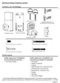
Page 21 INSTRUCTIONS D’INSTALLATION Contenu de l’emballage Outils requis Outils requis pour l’installation sur les portes pré-percées : • Tournevis Phillips Outils requis pour l’installation sur les portes qui exigent un perçage : • Perceuse • Ruban à mesurer • Crayon • Scie-cloche de 2-1/8 po (54 m...
Page 24 - PRÉPAREZ LA PORTE ET LE MONTANT DE PORTE; REMARQUE :
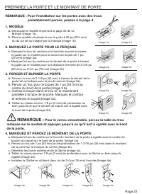
Page 22 REMARQUE : Pour l’installation sur les portes avec des trous préalablement percés, passez à la page 4. 1. MODÈLE a. Découpez le modèle imprimé à la page 35 de ce Manuel (Image 1a) . b. Pliez le modèle et placez-le sur la porte à 36 po (915 mm) du du sol tel qu’indiqué par la marque (Image 1b...
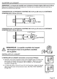
Page 25 - Pour le verrou encastrable, percez la taille du trou; AJUSTER LE LOQUET; REMARQUE : La partie courbée du loquet; INSTALLER LE LOQUET; TIRER
Page 23 5. INSTALLER LE LOQUET (nécessite un tournevis Phillips) a. Assurez-vous que la plaque avant soit à égalité avec la porte. Ne pas forcer le loquet dans la mortaise à égalité. Taillez au ciseau le matériel en excès, au besoin, afin d’obtenir un fini presque encastré. (Image 5a). b. À l’aide d...
Page 26 - FIXER L’ENSEMBLE EXTÉRIEUR À LA PORTE; INSTALLATION DE L’ENSEMBLE EXTÉRIEUR; INSTALLEZ L’ASSEMBLAGE EXTÉRIEUR
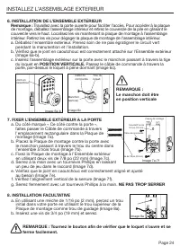
Page 24 REMARQUE : Le manchon doit être en position verticale Câble de commande Manchon (Vertical) Trou du loquet Image 6a-b Image 6c 7. FIXER L’ENSEMBLE EXTÉRIEUR À LA PORTE a. Du côté marqué « Ce côté contre la porte », faites passer le Câble de commande à travers l’emplacement rectangulaire dans ...
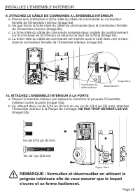
Page 27 - INSTALLEZ L’ENSEMBLE INTÉRIEUR; ATTACHEZ LE CÂBLE DE COMMANDE À L’ENSEMBLE INTÉRIEUR; dans le connecteur femelle de l’Ensemble intérieur (Image 9d).; ATTACHEZ L’ENSEMBLE INTÉRIEUR À LA PORTE; REMARQUE : Verrouillez et déverrouillez en utilisant la
Page 25 INSTALLEZ L’ENSEMBLE INTÉRIEUR 9. ATTACHEZ LE CÂBLE DE COMMANDE À L’ENSEMBLE INTÉRIEUR a. Prenez soin d’attacher la fiche mâle du câble de commande au connecteur femelle de l’Ensemble intérieur (Image 9a). b. Ne pas forcer la fiche mâle du câble de commande dans le connecteur femelle de l’En...
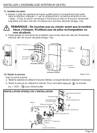
Page 28 - Avec la porte ouverte; INSTALLATION APERÇU DE L’INSTALLATION; REMARQUE : Ne touchez pas au clavier avant que la lumière
Page 26 11. Installer les piles a. Insérez 4 piles AA alcalines de haute qualité dans le compartiment des piles dans la direction indiquée +/- sur le compartiment. La serrure émettra un son « beep » 2 fois, le clavier numérique s’illuminera en bleu et le bouton Honeywell clignotera vert deux fois af...
Page 29 - INSTRUCTIONS D'EMPLOI; Aperçu de l'ensemble extérieur; Voyant; Paramètres réglés en usine
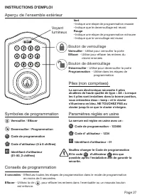
Page 27 INSTRUCTIONS D'EMPLOI Aperçu de l'ensemble extérieur Voyant lumineux Vert • Indique une étape de programmation réussie • Indique que le déverrouillage est réussi Rouge • Indique une étape de programmation échouée • Indique que le verrouillage est réussi La serrure électronique nécessite 4 pi...
Page 31 - SUPPRIMER UN CODE D'UTILISATEUR EXISTANT OU PRÉDÉFINI; RÉGLER OU ANNULER LE VERROUILLAGE AUTOMATIQUE
Page 29 Régler le Verrouillage automatique : Écoutez pour 1 « beep » et le voyant lumineux s'allume en vert SUPPRIMER UN CODE D'UTILISATEUR EXISTANT OU PRÉDÉFINI L'unité est fournie avec un Identifiant d'utilisateur réglé en usine ID = 01 pour le Code d’utilisateur UC = 1234. IMPORTANT : Pour suppri...
Page 32 - REMARQUE : Si vous appuyez uniquement sur pendant; demeurera en mode vacances.
Page 30 Mode Vacanes 10 1 PC Après 4 tentatives incorrectes de saisie du code, un avertissement sonore se fait entendre : Le clavier s’éteint pendant 30 secondes. Période de « Lock out » sécurisée Vous pouvez « supprimer » ou « allumer » le son sur votre serrure en entrant le suivant. (Le réglage en...
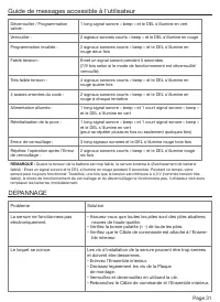
Page 33 - DÉPANNAGE; Guide de messages accessible à l'utilisateur
Page 31 DÉPANNAGE Problème Solution La serrure ne fonctionnera pas électroniquement. • Assurez-vous que toutes les piles sont des piles alcalines neuves de haute qualité. • Vérifiez la bonne polarité (+ -) de toute les piles. • Vérifiez que le Câble de commande est attaché à l'Ensem- ble intérieur. ...
Page 34 - AIDE AU CONSOMMATEUR
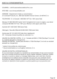
Page 32 COURRIEL : [email protected] SITE WEB : www.honeywellsafes.com ADRESSE : Département d’aide au consommateur LH Licensed Products, Inc., 860 East Sandhill Avenue Carson, CA 90746 É.-U. TÉLÉPHONE : É.-U./Canada 1-800-860-1677 Ext. 1801 (sans frais) Mexique 01-800-288-2872 Après l’arrêt l’enreg...
Page 35 - Fiche de programmation
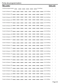
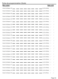
Page 33 Mes codes : Date créé Code de programmation (6 chiffres) / / Code d’utilisateur 01 (4 à 8 chiffres) / / Code d’utilisateur 02 (4 à 8 chiffres) / / Code d’utilisateur 03 (4 à 8 chiffres) / / Code d’utilisateur 04 (4 à 8 chiffres) / / Code d’utilisateur 05 (4 à 8 chiffres) / / Code d’utilisate...
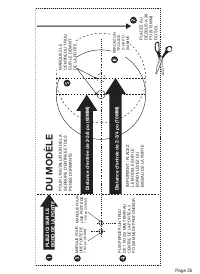
Page 37 - DU MODÈLE; PLIEZ ICI SUR LE BORD DE LA POR
Page 35 THEN DRILL 1” (25mm) HOLE IN CENTER DOOR OF EDGE 2” (50mm) IN DEPTH MARK FOR 1-3/4” (45mm) DOOR DRILL 2-1/8” (54mm) HOLE MARK FOR 1-3/8” (35mm) DOOR IMPO RT ANT! PLACE TEMPL AT E ON HIGH EDGE OF DOOR BEVEL DU MODÈLE Distance d'entrée de 2-3/8 po (60MM) Distance d'entrée de 2-3/4 po (70MM) PL...
Page 39 - composantes électroniques
Page 37 Garantie à vie limitée sur le mécanisme et le fini / Garantie limitée de 1 an sur les composantes électroniques Ce produit est livré avec un garantie à vie limitée sur le mécanisme et le fini et une Garantie limitée de 1 an sur les composantes électroniques au consommateur résidentiel origin...
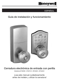
Page 41 - ¡Lea este manual cuidadosamente; Guía de instalación y funcionamiento; ESPAÑOL
Page 39 La marque de commerce de Honeywell est utilisée sous licence de Honeywell International Inc. Honeywell International Inc. ne fait aucune représentation ou garantie concernant ce produit. www.honeywellsafes.com Modelos 8732001, 8732101, 8732301, 8732401 ¡Lea este manual cuidadosamente antes d...
Page 42 - Índice; INSTRUCCIONES DE INSTALACIÓN
Page 40 Índice INSTRUCCIONES DE INSTALACIÓN Contenido del paquete / Herramientas necesarias .................................... Página 41 Preparar la puerta y el quicio ....................................................................... Página 42 Ajustar el pestillo / Instalar el pestillo ........
Page 43 - Contenido del paquete
Page 41 INSTRUCCIONES DE INSTALACIÓN Contenido del paquete Herramientas necesarias Herramientas necesarias para la instalación En puertas perforadas previamente: • Destornillador de cruz Herramientas necesarias para la instalación en puertas que requieren perforación: • Taladro • Cinta métrica • Láp...
Page 44 - PREPARAR LA PUERTA Y EL QUICIO
Page 42 NOTA: Para instalar en puertas con agujeros perforados previamente vaya a la página 4e. 1. PLANTILLA a. Corte la plantilla impresa en la página 55 de este manual (Figura 1a). b. Doble la plantilla y ubíquela en la puerta a 36” (915mm) del piso según lo marcado (Figura 1b). 2. MARQUE LA PUERT...
Page 45 - INSTALE EL PESTILLO (se necesita el destornillador de cruz); AJUSTAR EL PESTILLO; HALE; NOTA: La parte curva del pestillo debe
Page 43 5. INSTALE EL PESTILLO (se necesita el destornillador de cruz) a. Asegúrese de que el frente de la placa esté nivelado con la puerta. No fuerce el pestillo en la muesca de nivelación. Cincele el material sobrante si es necesario para que quede nivelado (Figura 5a). b. Con dos de los tornillo...
Page 46 - INSTALAR EL CONJUNTO EXTERIOR
Page 44 7. ASEGURE EL CONJUNTO EXTERIOR A LA PUERTA a. Desde el lado marcado “Este lado contra la puerta”, dirija el cable de control a través de la ranura rectangular en la placa de montaje (Figura 7a). b. Coloque la placa de montaje contra la puerta y haga que el extremo final pase a través del ag...
Page 47 - FIJE EL CABLE DE CONTROL AL CONJUNTO INTERIOR
Page 45 INSTALAR EL CONJUNTO INTERIOR Tornillos de 5/16” (8mm) Tornillo de 1” (25mm) NOTA: Cierre y abra con el pomo interior para ver si el pestillo del cerrojo abre y cierra fácilmente. Figura 10a-b Figura 9a-d 9. FIJE EL CABLE DE CONTROL AL CONJUNTO INTERIOR a. Tenga cuidado de sujetar el enchufe...
Page 48 - DESCRIPCIÓN GENERAL DE LA INSTALACIÓN; NOTA: No toque el teclado hasta que la luz azul esté apagada.
Page 46 11. Instalación de las baterías a. Inserte 4 baterías AA alcalinas de alta calidad en el compartimiento de baterías en la dirección marcada +/- en el compartimiento. El cerrojo pitará 2 veces, el teclado numérico se iluminará de azul y el botón Honeywell destellará dos veces en verde para in...
Page 49 - INSTRUCCIONES DE FUNCIONAMIENTO; Descripción general del conjunto exterior; Luz; Configuraciones de fábrica
Page 47 INSTRUCCIONES DE FUNCIONAMIENTO Descripción general del conjunto exterior Luz indicadora Verde • Indica un paso exitoso de programación • Indica una apertura exitosa Rojo • Indica un paso fallido de programación • Indica un cierre exitoso Las cerraduras electrónicas necesitan (4) baterías AA...
Page 51 - ELIMINAR UN CÓDIGO DE USUARIO EXISTENTE O PRECONFIGURADO; ESTABLEZCA O CANCELE EL CIERRE AUTOMÁTICO
Page 49 DESACTIVAR: Mientras aún esté en modo de cierre automático, abra la puerta usando PC , en los próximos 10 segundos debe mover la perilla manualmente hasta que esté en posición de cerrado; espere más de 2 segundos para mover la perilla de regreso hacia la posición de abierto. El modo de cierr...
Page 52 - NOTA: Si solo presiona el botón durante más de 3 segundos,; , el sistema permanecerá
Page 50 10 1 PC Si se ingresa 4 veces un código incorrecto, sonará una advertencia y la luz LED roja brillará: el teclado numérico se apagará por 30 segundos. Período de bloqueo seguro Usted puede “silenciar” o “encender el sonido” de su cerradura al introducir lo siguiente. (La configuración de fáb...
Page 53 - RESOLUCIÓN DE PROBLEMAS DE INSTALACIÓN; Problema; GUÍA DE MENSAJES DE USO FÁCIL PARA EL CONSUMIDOR
Page 51 NOTA: Si solo presiona el botón durante más de 3 segundos, pero no ingresa PC , el sistema permanecerá en el Modo vacaciones. DESACTIVAR: Para desactivar el Modo vacaciones, debe presionar y mantener durante más de 3 segundos, luego ingrese PC para abrir la puerta. El Modo vacaciones está ah...
Page 54 - ASISTENCIA AL CONSUMIDOR
Page 52 CORREO ELECTRÓNICO: [email protected] SITIO WEB: www.honeywellsafes.com DIRECCIÓN: Consumer Assistance Dept. LH Licensed Products, Inc., 860 East Sandhill Avenue Carson, CA 90746 USA TELÉFONO: EE.UU./Canadá 1800-860-1677 Ext. 1801 (número gratuito) México 01-800-288-2872. Luego de que la gra...
Page 55 - Registro de programación
Page 53 Mis códigos: Fecha de creación Código de programación (6 dígitos) / / Código de usuario 01 (4-8 dígitos) / / Código de usuario 02 (4-8 dígitos) / / Código de usuario 03 (4-8 dígitos) / / Código de usuario 04 (4-8 dígitos) / / Código de usuario 05 (4-8 dígitos) / / Código de usuario 06 (4-8 d...
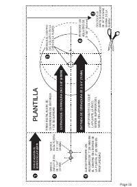
Page 57 - PLANTILLA
Page 55 THEN DRILL 1” (25mm) HOLE IN CENTER DOOR OF EDGE 2” (50mm) IN DEPTH MARK FOR 1-3/4” (45mm) DOOR DRILL 2-1/8” (54mm) HOLE MARK FOR 1-3/8” (35mm) DOOR IMPO RT ANT! PLACE TEMPL AT E ON HIGH EDGE OF DOOR BEVEL PLANTILLA ENTRADA DE CERRADURA DE 2-3/8” (60MM) ENTRADA DE CERRADURA DE 2-3/4” (70MM) ...
Page 59 - para electrónicos
Page 57 Garantía limitada mecánica y de acabado de por vida / Garantía limitada de 1 año para electrónicos Este producto viene con una garantía limitada mecánica y de acabado de por vida y una garantía limitada de un año para electrónicos para el consumidor original residencial, por defectos de mate...