Page 2 - LIMITED WARRANTY AND LIMITATION OF LIABILITY; enforceability of any other provision.
LIMITED WARRANTY AND LIMITATION OF LIABILITY Each Fluke product is warranted to be free from defects in material and workmanship under normal use and service. The warranty period is three years and begins on the date of shipment. Parts, product repairs, and services are warranted for 90 days. This w...
Page 3 - Table of Contents; Title Page
i Table of Contents Title Page Introduction .................................................................................................................... 1 Contacting Fluke ............................................................................................................ 2 Safety In...
Page 5 - iii; List of Tables; Table Title
iii List of Tables Table Title Page 1. Symbols ................................................................................................................................ 4 2. Unpack List ..............................................................................................................
Page 7 - List of Figures; Figure
v List of Figures Figure Title Page 1. VFD Low Pass Filter ............................................................................................................. 18 2. Measuring AC and DC Voltage ............................................................................................. 19 ...
Page 9 - Introduction
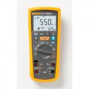
1 Introduction The Fluke 1587 FC, 1587, 1587T, and 1577 are battery-powered, true-RMS insulation multimeters (the Product or Meter) with a 6000-count display. Although this manual describes the operation of all models, all illustrations and examples assume use of Model 1587 FC. The Meter measures or...
Page 10 - Users Manual; Contacting Fluke; Or, visit Fluke’s website at; Safety Information; identifies conditions and procedures that are; Caution; identifies conditions and; Warning
1587 FC/1587/1577 Users Manual 2 Contacting Fluke To contact Fluke, call one of the following telephone numbers: • Technical Support USA: 1-800-44-FLUKE (1-800-443-5853) • Calibration/Repair USA: 1-888-99-FLUKE (1-888-993-5853) • Canada: 1-800-36-FLUKE (1-800-363-5853) • Europe: +31 402-675-200 • Ja...
Page 11 - ) shows to prevent incorrect
Insulation Multimeter Safety Information 3 • Keep fingers behind the finger guards on the probes. • Do not exceed the Measurement Category (CAT) rating of the lowest rated individual component of a Product, probe, or accessory. • Use the Product only as specified, or the protection supplied by the P...
Page 12 - Symbol Description Symbol
1587 FC/1587/1577 Users Manual 4 Table 1. Symbols Symbol Description Symbol Description WARNING.RISK OF DANGER. WARNING. HAZARDOUS VOLTAGE. Risk of electric shock. Consult user documentation. Battery (Low battery when shown on display.) AC (Alternating Current) Earth DC (Direct Curre...
Page 13 - Unpack List; Table 2 is a list of accessories included with your Product.; Accessories
Insulation Multimeter Unpack List 5 Unpack List Table 2 is a list of accessories included with your Product. Table 2. Unpack List Accessory Model 1587, 1587T, 1587 FC 1577 Leads TL224 TL224 Probes TP74 TL74 Clips AC285 AC285 Holster Yes Yes Hard Case Yes Yes K Type Thermocouple Yes No Remote Probe Y...
Page 14 - Hazardous Voltage; symbol is displayed.; Test Lead Alert; shows momentarily when you move
1587 FC/1587/1577 Users Manual 6 Hazardous Voltage To alert you to the presence of a potentially hazardous voltage, when the Meter detects a voltage ≥ 30 V or a voltage overload ( ), the Z symbol is displayed. Test Lead Alert To remind you to check that the test leads are in the correct terminals...
Page 15 - Rotary Switch Positions; Table 4. Rotary Switch Selections; AC voltage with 800 Hz VFD low-pass filter.
Insulation Multimeter Rotary Switch Positions 7 Rotary Switch Positions Turn the Meter on by selecting any measurement function. The Meter presents a standard display for that function (range, measurement units, modifiers, etc.). Use the blue button to select any rotary switch alternate functions (l...
Page 16 - Switch
1587 FC/1587/1577 Users Manual 8 Table 4. Rotary Switch Selections (cont.) Switch Position Measurement Function 158 7 F C 1 5 87 158 7T 1 5 77 k Temperature from - 40 ° C to + 537 ° C (- 40 ° F to + 998 ° F). Celsius is the default temperature measurement unit. The temperature measurement you select...
Page 17 - Buttons; Button Description
Insulation Multimeter Buttons 9 Buttons Use the buttons to activate features that augment the function selected with the rotary switch. The buttons are shown and described in Table 5. Table 5. Buttons SAVE bav03f.eps 158 7 F C 1 5 87 158 7T 1 5 77 Button Description Press to freeze the displayed v...
Page 19 - Display; Model; Indicator Description
Insulation Multimeter Display 11 Display Display indicators are shown and described in Table 6. Error messages that may appear on the display are described in Table 7. Warning To prevent possible electric shock or personal injury, replace the battery when the low battery indicator ( ) shows to ...
Page 21 - Secondary display for insulation test voltage.; Auto Range; Display range in use.
Insulation Multimeter Display 13 Table 6. Display Indicators (cont.) Indicator Description 158 7 F C 158 7 158 7T 157 7 Secondary display for insulation test voltage. • • • • Auto Range ManualRange 610000 Display range in use. • • • • 2500V 1000V Source voltage rating for insulation test: 50, 1...
Page 22 - Table 7. Error Messages; Input Terminals; Input terminals are shown and described in Table 8.; Table 8. Input Terminal Descriptions
1587 FC/1587/1577 Users Manual 14 Table 7. Error Messages Message Description Appears on the primary display and indicates that the battery is too low for reliable operation. The Meter will not operate at all until the battery is replaced. The also appears when is on the primary display....
Page 23 - Insulation Multimeter; to any switch; OFF; Note
Insulation Multimeter Power-Up Options 15 Power-Up Options Holding a button down while turning the Meter on activates a power-up option. Power-up options allow you to use additional features and functions of the Meter. To select a power-up option, hold down the appropriate button indicated while tur...
Page 24 - AutoHold Mode; MIN MAX AVG Recording Mode
1587 FC/1587/1577 Users Manual 16 AutoHold Mode Warning To prevent electrical shock, do not use the Display AutoHold mode to determine if a circuit is live. Unstable or noisy readings will not be captured. In the AutoHold mode, the Meter holds the reading on the display until it detects a new sta...
Page 25 - Manual Ranging and Auto Ranging
Insulation Multimeter Manual Ranging and Auto Ranging 17 Manual Ranging and Auto Ranging The Meter has both Manual Range and Auto Range modes. • In the Auto Range mode, the Meter selects the range with the best resolution. • In the Manual Range mode, you override Auto Range and select the range your...
Page 26 - Figure 1. VFD Low Pass Filter; Basic Measurements; COM; ) test lead before connecting
1587 FC/1587/1577 Users Manual 18 Warning To prevent possible electric shock or personal injury, do not use the VFD Low-Pass Filter function to verify the presence of hazardous voltages. Voltages that are greater than what is indicated may be present. First, make a voltage measurement without the...
Page 27 - AC and DC Voltage; Figure 2. Measuring AC and DC Voltage
Insulation Multimeter Basic Measurements 19 AC and DC Voltage Volts AC Volts DC Millivolts DC bav05f.eps Figure 2. Measuring AC and DC Voltage
Page 28 - Figure 3. Measuring Temperature
1587 FC/1587/1577 Users Manual 20 Temperature (all 1587 Models) The Meter measures the temperature of a type-K thermocouple (included). Choose between degrees Celsius ( ° C) or degrees Fahrenheit ( ° F). 1587 FC: Press to toggle between ° C or ° F. 1587/1587T: Press r to toggle between ° C or ° F....
Page 29 - Resistance; Figure 4. Measuring Resistance; Figure 5. Measuring Capacitance
Insulation Multimeter Basic Measurements 21 Resistance . SAVE bav06f.eps Figure 4. Measuring Resistance Capacitance (all 1587 models) . SAVE bav07f.eps Figure 5. Measuring Capacitance
Page 30 - Continuity; Figure 6. Testing for Continuity
1587 FC/1587/1577 Users Manual 22 Continuity The continuity test features a beeper that sounds as long as a circuit is complete. The beeper allows you to perform quick continuity tests without having to watch the display. To test for continuity, set up the Meter as shown in Figure 6. The beeper soun...
Page 31 - Good Diode; Figure 7. Testing Diodes
Insulation Multimeter Basic Measurements 23 Diodes (all 1587 models) . Single Beep Good Diode Forward Bias Bad Diode Open Good Diode Reverse Bias TEST MIN MAX HOLD LO Bad Diode Shorted and TEST MIN MAX HOLD LO Constant Beep bav10f.eps Figure 7. Testing Diodes
Page 32 - AC or DC Current; Testing the Fuses; later in this manual.; Turn; power to the circuit under test, break circuit,; ON; power. To measure ac
1587 FC/1587/1577 Users Manual 24 AC or DC Current Warning To prevent personal injury or damage to the Meter: • Never attempt to make an in-circuit current measurement when the open-circuit potential to earth is >1000 V. • Check the Meter’s fuses before testing. See Testing the Fuses later in ...
Page 33 - Load
Insulation Multimeter Basic Measurements 25 Load Load TEST MIN MAX HOLD LO DC Display Load bav11f.eps Figure 8. Measuring AC or DC Current
Page 34 - Insulation; Fuse Test
1587 FC/1587/1577 Users Manual 26 Insulation Insulation tests should only be performed on dead circuits. Check the fuse before testing. See Fuse Test later in this manual. To measure insulation resistance, set up the Meter as shown in Figure 9 and follow the steps below: 1. Insert test probes in the...
Page 35 - Figure 9. Testing Insulation
Insulation Multimeter Basic Measurements 27 bav13f.eps Figure 9. Testing Insulation PI/DAR Polarization Index (PI) is the ratio of the 10-minute insulation resistance to the 1 minute insulation resistance. Dielectric Absorption Ratio (DAR) is the ratio of the 1-minute insulation resistance to the 30...
Page 37 - AC/DC Voltage Frequency; Figure 10. Measuring Frequency
Insulation Multimeter Basic Measurements 29 AC/DC Voltage Frequency AC/DC Current Frequency Load bav12f.eps Figure 10. Measuring Frequency
Page 38 - Fluke ConnectTM Wireless System; to activate the Product’s radio. See; Figure 11. Fluke ConnectTM
1587 FC/1587/1577 Users Manual 30 Fluke Connect™ Wireless System The Product supports the Fluke Connect™ Wireless System (may not be available in all regions). Fluke Connect™ is a system that wirelessly connects your Fluke test tools with an app on your smartphone or tablet. It can show measurements...
Page 39 - How to Clean; OK; Figure 12. Testing the Fuse
Insulation Multimeter How to Clean 31 How to Clean Periodically wipe the case with a damp cloth and mild detergent. Do not use abrasives or solvents. Dirt or moisture in the terminals can affect readings. Battery Test To test the batteries, press and turn to the rotary switch to the INSULATION pos...
Page 40 - Battery and Fuse Replacement; Description Part
1587 FC/1587/1577 Users Manual 32 Battery and Fuse Replacement Replace the fuse and batteries as shown in Table 10. Follow the steps below to replace the batteries. Warning To prevent possible electrical shock, fire, or personal injury: • Replace the batteries when the battery indicator ( ) sho...
Page 41 - General Specifications
Insulation Multimeter General Specifications 33 General Specifications Maximum Voltage Applied to any Terminal and Common .................................... 1000 V Fuse Protection for mA input .................................. 0.44 A, 1000 V, IR 10 kA Batteries ......................................
Page 43 - Electrical Specifications; AC Voltage Measurement
Insulation Multimeter Electrical Specifications 35 Electrical Specifications AC Voltage Measurement Accuracy (all 1587 models) Range Resolution 50 Hz to 60 Hz ± (% of Rdg + Counts) 60 Hz to 5000 Hz ± (% of Rdg + Counts) 600.0 mV 0.1 mV ± (1 % + 3) ± (2 % + 3) 6.000 V 0.001 V ± (1 % + 3) ± (2 % + 3) ...
Page 44 - DC Voltage Measurement
1587 FC/1587/1577 Users Manual 36 1577 Accuracy Range Resolution 50 Hz to 60 Hz ± (% of Rdg + Counts) 600.0 mV 0.1 mV ± (2 % + 3) 6.000 V 0.001 V ± (2 % + 3) 60.00 V 0.01 V ± (2 % + 3) 600.0 V 0.1 V ± (2 % + 3) 1000 V 1 V ± (2 % + 3) AC Conversion ................................................... ...
Page 45 - DC Millivolts Measurement; DC and AC Current Measurement
Insulation Multimeter Electrical Specifications 37 DC Millivolts Measurement Range Resolution Accuracy all 1587 models ± (% of Rdg + Counts) Accuracy 1577 ± (% of Rdg + Counts) 600.0 mV dc 0.1 mV ± (0.1 % + 1) ± (0.2 % + 1) DC and AC Current Measurement Range Resolution Accuracy all 1587 models ± (%...
Page 46 - Ohms Measurement; Continuity Test
1587 FC/1587/1577 Users Manual 38 Ohms Measurement Range Resolution Accuracy all 1587 models [1] +(% of Rdg+Counts) Accuracy 1577 [1] +(% of Rdg+Counts) 600.0 Ω 0.1 Ω ± (0.9 % + 2) ± (1.2 % + 2) 6.000 k Ω 0.001 k Ω 60.00 k Ω 0.01 k Ω 600.0 k Ω 0.1 K Ω 6.000 M Ω 0.001 M Ω 50.0 M Ω [2] 0.01 M Ω ± (1.5...
Page 47 - Frequency Counter Sensitivity (all 1587 models); Temperature Measurement (all 1587 models)
Insulation Multimeter Electrical Specifications 39 Frequency Counter Sensitivity (all 1587 models) Input Range V ac Sensitivity (RMS Sine Wave) [1] DC Trigger Levels [1] to 20 kHz [2] 5 Hz to 20 kHz 20 kHz to 100 kHz 600.0 mV ac 100.0 mV 150.0 mV na 6.0 V 1.0 V 1.5 V -400.0 mV and 2.5 V 60.0 V 10.0 ...
Page 48 - Insulation Specifications
1587 FC/1587/1577 Users Manual 40 Insulation Specifications Measurement Range Model 1587, 1587 FC ................................. 0.01 M Ω to 2 G Ω Model 1577 ................................................. 0.1 M Ω to 600 M Ω Model 1587T ............................................... 0.01 M Ω t...