Page 3 - Table of Contents; Title
i Table of Contents Title Page Introduction ........................................................................................................... 1 How to Contact Fluke............................................................................................ 1 Safety Information ...............
Page 5 - OL; Test Lead Alert; XW; Warning; LEAd
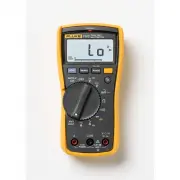
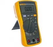
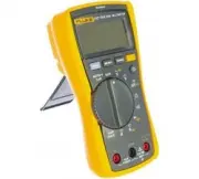
1 Introduction The Fluke Model 110, Model 113, Model 114, Model 115, and Model 117 (the Meter or Product) are battery-powered, true-rms multimeters with a 6000-count display and a bar graph. This manual applies to all models. All figures show the Model 117 unless indicated. How to Contact Fluke To c...
Page 6 - Users Manual; Product Familiarization; Features
110/113/114/115/117 Users Manual 2 Product Familiarization The manual explains features for multiple models. Because models have different features, not all of the information in the manual may apply to your Meter. Use Table 1 to identify the features of your Meter. Features Table 1 is a list of the...
Page 7 - Display; Table; Symbol; VWX; LoZ
True-rms Multimeter Product Familiarization 3 Display Table 2 is a list of the features for each display. Table 2. Display No. Symbol Meaning Model w The Meter is in the VoltAlert™ non-contact voltage detect mode. 117 s The Meter function is set to Continuity. 110, 113, 114, 115, 117 R The Meter fun...
Page 8 - Terminals; Auto Volts; Description; Input terminal for measuring ac and dc current to 10 A.
110/113/114/115/117 Users Manual 4 Terminals Table 3 is a list of terminals on the Meter. No. Symbol Meaning Model Auto Volts The Meter is in the Auto Volts function. 114, 117 Auto Autoranging. The Meter selects the range for best resolution. 110, 113, 114, 115, 117 Manual Manual ranging. User sets ...
Page 9 - Error Messages; Note; Table 4. Error Messages; bAtt
True-rms Multimeter Product Familiarization 5 Error Messages Table 4 is a list of error messages for the Meter. Battery Saver™ (Sleep Mode) If the Meter is ON, but inactive and not connected to voltage for more than 20 minutes, the display goes blank to save battery life.To use the Meter, press any ...
Page 10 - Display HOLD; Backlight; Manual; Button; bEEP
110/113/114/115/117 Users Manual 6 Display HOLD XW Warning To avoid electric shock, when Display HOLD is activated, be aware that the display will not change when you apply a different voltage. In the Display HOLD mode, the Meter freezes the display.1. Push f to activate Display HOLD. ( K shows on t...
Page 11 - Making Basic Measurements; ) test lead before connecting; Measuring Resistance
True-rms Multimeter Product Familiarization 7 Making Basic Measurements When connecting the test leads to the circuit or device, connect the common ( COM ) test lead before connecting the live lead; when removing the test leads, remove the live lead before removing the common test lead. XW Warning T...
Page 12 - Measuring AC and DC Voltage
110/113/114/115/117 Users Manual 8 Measuring AC and DC Voltage Using Auto Volts Selection (114, 117) With the function switch in the x position, the Meter automatically selects a dc or ac voltage measurement based on the input applied between the V or + and COM jacks. This function also sets the Met...
Page 14 - Hz
110/113/114/115/117 Users Manual 10 Measuring Capacitance (113, 115, 117) Measuring Frequency (115, 117) XW Warning To avoid electrical shock, disregard the bar graph for frequencies >1 kHz. If the frequency of the measured signal is >1 kHz, the bar graph and Z are unspecified. The Meter measu...
Page 15 - LCAP; shows on the display.
True-rms Multimeter Product Familiarization 11 Detecting AC Voltage Presence (117) To detect the presence of ac voltage, place the top of the Meter close to a conductor. The Meter gives an audible as well as visual indication when voltage is detected. The sensitivity settings are:• Lo : use on flush...
Page 16 - Using the Bargraph; ) to the right and a polarity
110/113/114/115/117 Users Manual 12 Testing Diodes (113, 115, 117) Using the Bargraph The bar graph is like the needle on an analog meter. It has an overload indicator ( ) to the right and a polarity indicator ( + ) to the left. Because the bar graph is much faster than the digital display, the bar ...
Page 17 - Maintenance; Test fuse as shown in Figure; Figure 1. Test the Fuse; Replacing the Battery and Fuse; See Figure; Figure 2. Disassembly; OK
True-rms Multimeter Maintenance 13 Maintenance Maintenance of the Meter consists of battery and fuse replacement, as well as case cleaning. Testing the Fuse (115, 117) Test fuse as shown in Figure 1 . Figure 1. Test the Fuse Replacing the Battery and Fuse XW Warning To avoid shock, injury, or damage...
Page 18 - Cleaning
110/113/114/115/117 Users Manual 14 To remove the battery door for battery replacement:1. Remove the test leads from the Meter.2. Remove the battery door screw.3. Use the finger recess to lift the door slightly.4. Lift the door straight up to separate it from the case.5. The battery fits inside the ...
Page 19 - Specifications
True-rms Multimeter Specifications 15 Specifications Accuracy is specified for 1 year after calibration, at operating temperatures of 18 °C to 28 °C, with relative humidity at 0 % to 90 %.Extended specifications are available at www.Fluke.com. Maximum voltage between any terminal and earth ground .....
Page 20 - Table 6. Accuracy Specifications
110/113/114/115/117 Users Manual 16 Table 6. Accuracy Specifications Function Range Resolution Accuracy ± ([% of Reading] + [Counts]) Model DC Millivolts 600.0 mV 0.1 mV 0.5 % + 2 110, 114, 115, 117 DC Volts 6.000 V 0.001 V 0.5 % + 2 110, 114, 115, 117 60.00 V 0.01 V 600.0 V 0.1 V DC, 45 to 500 Hz 5...