Emerson 1F83C-11NP - Installation Manual
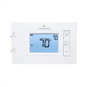
Emerson 1F83C-11NP Thermostat – Installation Manual, read for free online in PDF format. We hope this helps you resolve any issues you may have. If you have further questions, please contact us through the contact form.


Table of Contents:
- Page 2 – THERMOSTAT INSTALLATION; WIRING; WARNING; CAUTION; Precautions; • Do not exceed the specification ratings.; Désignation de la borne; INSTALLA; CÂBLAGE; et ils décrivent les fonctions des bornes du thermostat.; A VER; MISE EN GARDE; Précautions; Une
- Page 3 – INSTALLER MENU; the INSTALLER’S MENU press the; Battery Location; MENU DE L ’INST; Emplacement des piles
- Page 4 – TEST EQUIPMENT; Move fan switch to On position. The blower should begin to operate.; MISE À L; Système de chauffage; (chauffage en marche
- Page 5 – THERMOSTAT OVERVIEW; the location/operation of the thermostat buttons and switches.; SEE TROUBLESHOOTING; USING THE THERMOSTAT; ” appears in the display, new premium brand AA alkaline batteries; ” is displayed, install new batteries before leaving.; APERÇU; Avant d’utiliser le thermostat, vous de; UTILISATION; Lorsque «; » s’affiche, installez de nouvelles piles a
- Page 6 – until the icon appears (this can; USER MENU; Menu; Verrouillage du clavier; – Afin d’; Menu; MENU DE; Menu; pour modifier le réglage.
- Page 7 – TROUBLESHOOTING; DÉPANNA
- Page 8 – Resetting the Thermostat or Thermostat Settings; minutes. This reset; and; light; Réinitialisation du thermostat ou de ses réglages; piles en place, il faudra remplacer le thermostat.; et de; rétroéclairage; et gardez-les enfoncés jusqu’; GUIDE DE DÉP ANNA; LIGNE D’ ASSIST; cancer and birth defects and other reproductive harm.
Electrical Rating:
Battery Power ..................................... mV to
30
VAC, NEC Class II,
50/60
Hz
Input-Hardwire ....................................
20
to
30
VAC, NEC Class II,
50
/
60
Hz
Terminal Load ..........................................
1.5
A per terminal,
2.5
A maximum all terminals combined
Setpoint Range ........................................
45°
to
99°
F (
7°
to
37° C)
Rated Differentials:
Fast
Med
Slow
Heat (@
6
°F/ Hr) ..................................
0.5°F 0.75°F 1.9°F
Cool (@
6
°F/ Hr) ..................................
0
.
9°F 1.2°F 1.7°F
Operating Ambient ..................................
32°F to +105°F (0° to +41°C)
Display Temperature Range ....................... 32°F to +99°F (0 to 37°C)
Operating Humidity .................................
90
% non-condensing max
Shipping Temperature Range ...................
-20
°F to +
150
°F
(-29° to +65°C)
Thermostat Dimensions ...........................
3-3/4” H x 6” W x 1-1/8” D
PART NO.
37-747900
4
Replaces 37-747900
3
2222
1F83C-11NP
(Non-Programmable)
Installation and Operating Instructions
Single Stage Thermostat
Battery Powered or Hardwired with Common
Thermostat Applications
Maximum
Stages
Heat/Cool
Conventional Gas, Oil, Electric (mV and
24
V), Heat Only, Cool Only or Heat/
Cool Systems
1/1
Heat Pump (air source or geothermal)
with no Aux. Heat
1/1
Thermostat Installation
2-4
Wiring
2
Installer Menu
3-4
Using the Thermostat
5-7
Thermostat Overview
5
User Menu
6
Thermostat Operation
6
Troubleshooting
7-8
Homeowner Help Line
8
INDEX
SPECIFICATIONS
www.copeland.
com/white-rodgers
Paramètres électriques :
Batterie
......................................................
20
à
30
V c.a., NEC classe II,
50
/
60
Hz
Câblé ..........................................................
20
à
30
V c.a., NEC classe II,
50
/
60
Hz
Charge à la borne
............................................
1,5
A par borne
,
2,5
A maximum pour toute
s les bornes combinée
s
Plage de
réglage .............................................
45
à
99
°
F (
7
à
37 °C)
Différentiel nominal
:
Rapide
Moyen
Lent
Chauffage (@
6
°F/h) .................................
0,5 °F
0,75 °F
1,9 °F
Climatisation (@ 6
°F/h) ............................
0
,
9 °F
1,2 °F
1,7 °F
T empé
rature ambiante de fonctionnement
...
32 °F à +105 °F (0 à +41 °C)
Plage de
tempér
atur
es affichées
......................
32 °F à +99 °F (0 à +37 °C)
Humidité de fonctionne
ment
.........................
90
% max. sans condensation
Plage de
température
s d’ expédition
...............
-20
°
F à +
150
°
F
(-29 à +65 °C)
Dimensions du thermostat .............................
3-3/4 po H x 6 po L x 1-1/8 po P
N
O
DE PIÈCE
37-747900
4
Remplace 37-747900
3
2222
1F83C-11NP
(non programmable
)
Instructions d’installation et d’utilisation
Thermosta
t avec thermopompe
Alimentation par piles ou câblée avec fil commun
Applications du thermostat
Nombre
maximum
d’étages
chauffage/
climatisation
Systèmes au gaz conventionnels, au
mazout, à l’électricité (
mV et
24
V),
chauffage seulement, climatisation
seulement ou chauffage et climatisation
1/1
Thermopompe (source d’air ou
géothermique) sans chauffage auxiliaire
1/1
Installation du thermostat
2-4
Câblage
2
Menu de l’installateur
3-4
Utilisation du thermostat
5-7
Aperçu du thermostat
5
Menu de l’utilisateur
6
Fonctionnement du thermostat
6
Dépannage
7-8
Ligne d’assistance pour les
propriétaires
8
INDEX
SPÉCIFICATIONS
Optional Accessory: Wall
Cover-Up Plate
F61-2663
,
6 3/4
” W x
4 1/2
” H
Accessoire en op
tion :
plaque murale F61-2663,
6 3/4 po L x 4 1/2 po H
www.copeland.
com/white-rodgers
ATTENTION: AVIS RELATIF AU MERCURE
Ce produit ne contient pas de mercure, mais il peut remplacer une
unité qui en contient.
Le mercure et les produits contenant du
mercure ne doivent pas être jetés dans les ordures ménagères.
Ne touchez pas au mercure déversé.
Mettez des gants non
absorbants pour ramasser le mercure, puis placez-le dans un
contenant étanche. Pour jeter correctement un produit contenant du
mercure ou un contenant scellé qui renferme du mercure, placez-le
dans un contenant d’expédition approprié.
Consultez le site
www.thermostat-recycle.org
pour savoir où expédier un produit
contenant du mercure.
ATTENTION: MERCURY NOTICE
This product does not contain mercury. However, this product may
replace a product that contains mercury.
Mercury and products
containing mercury must not be discarded in household trash.
Do not touch any spilled mercury.
Wearing non-absorbent gloves,
clean up any spilled mercury and place in a sealed container. For
proper disposal of a product containing mercury or a sealed container
of spilled mercury, place it in a suitable shipping container. Refer to
www.thermostat-recycle.org
for location to send the product
containing mercury.
"Loading the manual" means you need to wait until the file loads and becomes available for online reading. Some manuals are very large, and the time they take to appear depends on your internet speed.
Was this manual helpful?
About this manual
- Brand
- Emerson
- Model
- 1F83C-11NP
- Document type
- Installation Manual
- Category
- Thermostat
- Language(s)
- English, French
- Pages
- 8
- Format
Other Manuals for Emerson 1F83C-11NP
Summary
2 Terminal Designations Terminal Function RC* Power for Cooling RH* Power for Heating O/B Changeover Terminal-Energized in Heat (B) or Cool (O) for Heat Pump or Damper Systems Y** Cooling Relay G Fan Relay W** Heating Relay C Common wire for 24V (optional with batteries) *When both RC and RH wires a...
3 1.) Gas/Elec Switch If the system is a heat pump or electric furnace, the GAS/ELEC Switch must be set to Elec . If your system is a gas or oil furnace, the switch must be set to Gas . 2. ) O/B Terminal Switch The O/B switch on this thermostat is factory set to the O position. This will accommodate...
4 Installer’s Menu # (Hold Menu 8 Seconds) Description Default Setting (flashing icons) Settings 79 Fahrenheit or Celsius °F °F – Fahrenheit °C – Celsius 81 Temperature Display Adjustment (adjust the displayed “Room Temperature”) 0 -5 to +5 83 Continuous Display Light (keep the backlight always on –...
Ask a question
Related manuals
More Emerson Thermostats models
 Emerson 1E78-144 User Manual
 Emerson 1F75P-21NP User Manual
 Emerson 1F78-151 User Manual
 Emerson 1F80-361 User Manual
 Emerson 1F83C-11PR User Manual
 Emerson 1F83H-21PR User Manual
 Emerson 1F85U-42NP User Manual
 Emerson 1F85U-42PR User Manual
 Emerson 1F86-344 User Manual
 Emerson 1F95-1277 User Manual
 Emerson 1F95EZ-0671 User Manual
 Emerson 1F97-1277 User Manual
 Emerson P150 User Manual
 Emerson ST25 User Manual
 Emerson ST55 User Manual
 Emerson ST75 User Manual


