Page 2 - ENGLISH; Contents; APPROVED FOR RESIDENTIAL APPLIANCES; PLEASE READ ENTIRE INSTRUCTIONS BEFORE PROCEEDING.; Save these Instructions for the Local Electrical Inspector’s use.
2 ENGLISH Contents Important safety notice ................................................................................................................................................................................................ 3List of materials ................................................
Page 3 - IMPORTANT SAFETY NOTICE
3 I IMPORTANT SAFETY NOTICE I CAUTION FOR GENERAL VENTILATING USE ONLY. DO NOT USE TO EXHAUST HAZARDOUS OR EXPLOSIVE MATERIALS OR VAPOURS. I WARNING TO REDUCE THE RISK OF FIRE, ELECTRIC SHOCK, OR INJURY TO PERSONS, OBSERVE THE FOLLOWING: A. Use this unit only in the manner intended by the manufactur...
Page 4 - LIST OF MATERIALS; CAUTION
4 LIST OF MATERIALS Removing the packaging. I CAUTION Remove carton carefully, Wear gloves to protect against sharp edges. I WARNING Remove the protective film covering the product before putting into operation. Supplied Part Pieces Supplied Part Pieces Hood assembly and LED lamps already installed ...
Page 5 - PRODUCT DIMENSIONS; Product dimensions; Model; Installation clearances; NOTE; Venting requirements; For the most efficient and quiet operation:
5 PRODUCT DIMENSIONS Product dimensions I* - Metallic spacers Spacers has to be installed and used when cabinet depth is greater than 12”. E A B C F G H D I* I* Model EAS428S1 A 28 17 ⁄ 64 ” (71.8 cm) B 26” (66 cm) C 1 9 ⁄ 64 ” (2.9 cm) D 10¾” (27.3 cm) E 9 17 ⁄ 32 ” (24.2 cm) F 0 21 ⁄ 64 ” (.85 cm)...
Page 6 - Roof venting; Electrical requirements; WARNING; GROUNDING INSTRUCTIONS
6 Cold weather installations An additional back draft damper non return valve should be installed to minimize backward cold air flow and a thermal break should be installed to minimize conduction of outside temperatures as part of the vent system. The damper non return valve should be on the cold ai...
Page 7 - Installation instructions
7 Installation instructions Prepare location It is recommended that the vent system be installed before the range hood is installed. • Before making cutouts, make sure there is proper clearance within the ceiling or wall for vent fittings. • Making the cutout to the bottom of the cabinet may be easi...
Page 8 - Venting outside through the wall; cabinet
8 Venting outside through the wall 1 Measure from the bottom of the range hood liner to the horizontal centerline of the vent opening (A). A B C D A. Measurement AB. Horizontal centerline of vent opening C. Range hood linerD. 12” (30.5 cm) min. cabinet height 5 Remove the vent duct from the range ho...
Page 9 - Install range hood
9 Bracket Orientation for 36” (91.4 cm) Cabinet A B C D A. 30” (76.2 cm) cabinetB. Screws - 4.5 x 13 mm (8)C. Washers (optional)D. Mounting bracket (2) (position for 30” [76.2 cm cabinet) Move the bracket 6 ⁄ 16 ” (1 cm) from the bottom side of the cabinet 5 Install the vent system according to the ...
Page 10 - Connect the vent system; Vented Installations; Complete installation; Description of the hood; Controls
10 Connect the vent system Vented Installations 1 Connect the vent system to the range hood vent opening. Seal the connection with clamps. Non-Vented (recirculating) Installations 1 Connect the vent system to the range hood vent opening. Seal the connection with clamps. 2 Install charcoal filters. S...
Page 12 - ELICA North America; TWO-YEAR LIMITED WARRANTY; TO OBTAIN SERVICE UNDER WARRANTY; Damage or failure to the product caused by operator abuse.; WHO IS COVERED; Register your product in; year of factory
ELICA North America TWO-YEAR LIMITED WARRANTY TO OBTAIN SERVICE UNDER WARRANTY Owner must present proof of original purchase date. Please keep a copy of your dated proof of purchase (sales slip) in order to obtain service under warranty. PARTS AND SERVICE WARRANTY For the period of two (2) years fro...
Page 13 - FRANÇAIS; Table des matières; APPROUVÉ POUR LES APPAREILS DE TYPE RÉSIDENTIEL; VEUILLEZ LIRE CES INSTRUCTIONS AU COMPLET AVANT DE COMMENCER.; panneau avant de raccorder les fils de cet appareil.
13 FRANÇAIS Table des matières Avis de sécurité important .......................................................................................................................................................................................... 14Liste des pièces .......................................
Page 14 - AVIS DE SÉCURITÉ IMPORTANT
14 I AVIS DE SÉCURITÉ IMPORTANT I ATTENTION UTILISER CET APPAREIL À DES FINS DE VENTILATION GÉNÉRALE SEULEMENT. NE PAS UTILISER CET APPAREIL POUR ÉVACUER DES MATÉRIAUX OU DES VAPEURS DANGEREUX OU EXPLOSIFS. I AVERTISSEMENT POUR RÉDUIRE LES RISQUES D’INCENDIE, DE CHOC ÉLECTRIQUE ET DE BLESSURE, RESPE...
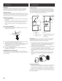
Page 15 - LISTE DES PIÈCES; ATTENTION; Pièces Fournies; Outils nécessaires; Exigences d’emplacement:
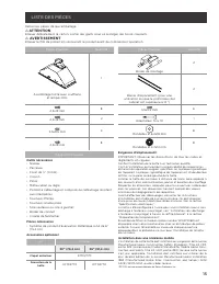
15 LISTE DES PIÈCES Retirer les pièces de leur emballage. I ATTENTION Enlever délicatement le carton, porter des gants pour se protéger des bords coupants. I AVERTISSEMENT Enlever le film de protection recouvrant le produit avant de commencer l’opération. Pièces Fournies Quantité Pièces Fournies Qua...
Page 16 - DIMENSIONS DU PRODUIT; Modèle; Dégagements de séparation; Exigences concernant l’évacuation; Pour un fonctionnement efficace et silencieux:
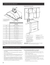
16 DIMENSIONS DU PRODUIT I* - Barres d’espacement Pour une utilisation lorsque la profondeur del cabinet est supérieure à 12“. E A B C F G H D I* I* Modèle EAS428S1 A 28 17 ⁄ 64 ” (71,8 cm) B 26” (66 cm) C 1 9 ⁄ 64 ” (2,9 cm) D 10¾” (27,3 cm) E 9 17 ⁄ 32 ” (24,2 cm) F 0 21 ⁄ 64 ” (,85 cm) G 14 9 ⁄ 1...
Page 17 - Décharge à travers le toit; Spécifications électriques; AVERTISSEMENT; INSTRUCTIONS DE MISE À LA TERRE
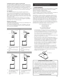
17 Installations dans les régions au climat froid On doit installer un clapet anti-retour valve supplémentaire à l’arrière pour minimiser le reflux d’air froid et incorporer un élément d’isolation thermique pour minimiser la conduction de chaleur par l’intermédiaire du conduit d’évacuation, de l’int...
Page 18 - Instructions d’installation; Préparation de l’emplacement; Ouverture découpée du placard pour la hotte; Mesures appropriées; Hauteur du placard Taille et forme du trou
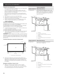
18 Instructions d’installation Préparation de l’emplacement • BIl est recommandé que l’installation du circuit d’évacuation soit réalisée avant celle de la hotte. • Avant de procéder aux découpages, vérifier que les dis- tances de séparation pour les raccords dans les cavités du plafond ou du mur so...
Page 19 - Décharge à l’extérieur, à travers le mur; Installation sans décharge à l’extérieur (recyclage) à travers; REMARQUE
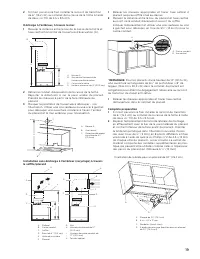
19 2 S’il n’est pas encore fixé, installer le raccord de transition de 6” (15,2 cm) au sommet de la caisse de la hotte à l’aide de deux vis T10 de 3,5 x 9,5 mm. Décharge à l’extérieur, à travers le mur 1 Mesurer la distance entre le bas de la caisse de la hotte et l’axe central horizontal de l’ouver...
Page 20 - Installation de la hotte
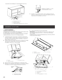
20 Orientation de la bride pour un placard de 36” (91.4 cm) A B C D A. Placard de 30” (76,2 cm)B. 8 vis - 4.5 x 13 mmC. Rondelles (facult tives)D. 2 brides de montage (position for 30” [76,2 cm) Déplacer le support 6 ⁄ 16 ” (1 cm) du fond côté de l’armoire 5 Installer le circuit d’évacuation selon l...
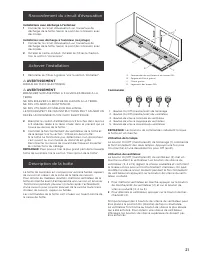
Page 21 - Raccordement du circuit d’évacuation; Installations avec décharge à l’extérieur; Achever l’installation; Description de la hotte
21 Raccordement du circuit d’évacuation Installations avec décharge à l’extérieur 1 Connecter le circuit d’évacuation sur l’ouverture de décharge de la hotte. Serrer le point de connexion avec des brides. Installation sans décharge à l’extérieur (recyclage) 1 Connecter le circuit d’évacuation sur l’...
Page 23 - GARANTIE DE DEUX ANS; POUR OBTENIR UN DEPANNAGE SOUS GARANTIE; Dégât ou panne du produit causé par une mauvaise utilisation.; QUI EST COUVERT; Demandez le service après-vente; Enregistrez votre produit sur; et obtenez une; de
ELICA North America GARANTIE DE DEUX ANS POUR OBTENIR UN DEPANNAGE SOUS GARANTIE Le propriétaire doit présenter une preuve de la date d’achat. Garder une copie de votre preuve d’achat datée (ticket de caisse) de façon à pouvoir bénéficier du service après-vente sous garantie. GARANTIE PIECES DE RECH...
Page 24 - ESPAÑOL; Contenido; APROBADO PARA APARATOS DE USO DOMÉSTICO; ANTES DE CONTINUAR, LEA LAS INSTRUCCIONES POR COMPLETO.; Entregue al propietario estas instrucciones junto con la unidad.; Advertencia de seguridad:; de servicio y desbloquee el panel.
24 ESPAÑOL Contenido Aviso de seguridad importante ................................................................................................................................................................................ 25Lista de materiales .....................................................
Page 25 - AVISO DE SEGURIDAD IMPORTANTE; FUNCIONAMIENTO
25 I AVISO DE SEGURIDAD IMPORTANTE I PRECAUCIÓN SÓLO PARA USO DE VENTILACIÓN GENERAL. NO UTILIZAR PARA EXPULSAR VAPORES O MATERIALES PELIGROSOS O EXPLOSIVOS. I ADVERTENCIA PARA REDUCIR EL RIESGO DE FUEGO, DESCARGA ELÉCTRICA O LESIONES PERSONALES, RESPETE LO SIGUIENTE: A. Utilice esta unidad solament...
Page 27 - LISTA DE MATERIALES; PRECAUCIÓN
27 LISTA DE MATERIALES Remoción de la confección I PRECAUCIÓN Quite la caja cuidadosamente, use guantes para protegerse contra los bordes afilados. I ADVERTENCIA Quite la película de protección que cubre el producto antes de ponerlo en funcionamiento. Piezas suministradas Piezas Piezas suministradas...
Page 28 - DIMENSIONES DE PRODUCTO; Modelo; Medidas de instalación; Requisitos de ventilación; Para obtener el funcionamiento más eficaz y silencioso:
28 DIMENSIONES DE PRODUCTO I* - Espaciadores metálicos Los espaciadores deben ser insta- lados cuando la profundidad del gabinete es mayor a 12”. E A B C F G H D I* I* Modelo EAS428S1 A 28 17 ⁄ 64 ” (71.8 cm) B 26” (66 cm) C 1 9 ⁄ 64 ” (2.9 cm) D 10¾” (27.3 cm) E 9 17 ⁄ 32 ” (24.2 cm) F 0 21 ⁄ 64 ” ...
Page 29 - Ventilación a través del; Requisitos eléctricos; ADVERTENCIA
29 Instalaciones en climas fríos Como parte del sistema de ventilación, se deberá instalar una compuerta de contratiro adicional para minimizar el flujo de aire frío hacia atrás, y un dispositivo de interrupción térmico para reducir la conducción de las temperaturas exteriores. La compuerta deberá e...
Page 30 - Instrucciones de instalación; Prepare la ubicación; Cortes al gabinete; Altura del gabinete Forma y tamaño del orificio
30 33 15 ⁄ 32 (85 cm) INSTRUCCIONES PARA LA CONEXIÓN A TIERRA • Esta campana para cocina debe estar conectada a tierra. • En caso de que se produzca un cortocircuito, la conexión a tierra reduce el riesgo de choque eléctrico al proporcionar un alambre de escape para la co- rriente eléctrica. Esta ca...
Page 32 - Instalación; NOTA
32 Orientación del soporte al gabinete de 30” (76.2 cm) A B C D A. Gabinete de 30” (76.2 cm)B. 8 tornillos - 4.5 x 13 mmC. Rondanas (opcionales)D. 2 soportes de montaje (posición para gabinetes de 30” [76.2 cm]) Orientación del soporte al gabinete de 36” (91.4 cm) A B C D A. Gabinete de 30” (76.2 cm...
Page 33 - Conecte el sistema de ventilación; Instalaciones con ducto de salida de aire; Complete la instalación; Descripción de la campana
33 C B A D A. 4 tornillos de hoja plana- 3.5 x 9.5 mmB. Panel frontalC. GabineteD. 2 tornillos - 4.2 x 15 mm Conecte el sistema de ventilación Instalaciones con ducto de salida de aire 1 Conecte el ducto del sistema de ventilación a la abertura de la campana de cocina. Selle la conexión con las abra...
Page 35 - A QUIÉN CONTACTAR; Norte América; Departamento de Servicio al Cliente; GARANTÍA LIMITADA DE DOS AÑOS; PARA OBTENER SERVICIO DENTRO DE GARANTÍA; Registre su producto en; año de garantía de
A QUIÉN CONTACTAR Norte América • Servicio Elic a North America , llame a 1-888 7 32 8 0 18 Latinoamérica • www.elica.com/asistencia • Par a el E st e de Canadá, llame a Servicios A GI a 1-888 651 2534. P regunt e por el Departamento de Servicio al Cliente • elica@servic ep owe r.com Par a ob t ener...