Triplett PQC300 - Manuals
User Manual Triplett PQC300


Summary
AC/DC TRMS H&W ANALYSIS CLAMP METER 4 1. Features • AC TRMS voltage • DC voltage and AC+CD TRMS voltage • Phase sequence • Active, reactive, apparent power and power factor on single-phase • Active, reactive, apparent energy on single-phase systems • AC voltage harmonics (1-25) and THD% up to 75...
5 2-4.CAUTIONS • Read and understand this user manual before operating the meter. • Improper use of this meter can cause damage, shock, injury or death. • Always remove the test leads before replacing the battery . • If the test leads need to be replaced, you must use a new one which should meet EN ...
9 3-4.Description of Internal Functions 3-4-1.Save Function 1. Press the Data Hold/Flashlight Button to freeze the result, the message “ Hold ” appears on the display. 2. Press the F1 (Save) Key to save the data in the instrument’s memory. 3-4-2.Relative Values 1. To activate the relative mode, pres...
Triplett Multimeters Manuals
-
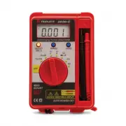 Triplett 2030
User Manual
Triplett 2030
User Manual
-
 Triplett 9055
User Manual
Triplett 9055
User Manual
-
 Triplett 9325
User Manual
Triplett 9325
User Manual
-
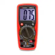 Triplett 9007A
User Manual
Triplett 9007A
User Manual
-
 Triplett 9007A-NIST
User Manual
Triplett 9007A-NIST
User Manual
-
 Triplett BBT858L
User Manual
Triplett BBT858L
User Manual
-
 Triplett CM1000
User Manual
Triplett CM1000
User Manual
-
 Triplett CM1000-NIST
User Manual
Triplett CM1000-NIST
User Manual
-
 Triplett CM1050
User Manual
Triplett CM1050
User Manual
-
 Triplett CM1050-NIST
User Manual
Triplett CM1050-NIST
User Manual
-
 Triplett CM1070
User Manual
Triplett CM1070
User Manual
-
 Triplett CM200
User Manual
Triplett CM200
User Manual
-
 Triplett CM200-NIST
User Manual
Triplett CM200-NIST
User Manual
-
 Triplett CM24
User Manual
Triplett CM24
User Manual
-
 Triplett CM400
User Manual
Triplett CM400
User Manual
-
 Triplett CM400-NIST
User Manual
Triplett CM400-NIST
User Manual
-
 Triplett CM450
User Manual
Triplett CM450
User Manual
-
 Triplett CM450-NIST
User Manual
Triplett CM450-NIST
User Manual
-
 Triplett CM600
User Manual
Triplett CM600
User Manual
-
Triplett CM600-NIST
User Manual