Triplett CM675IR - Manuals
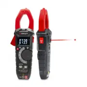
User Manual Triplett CM675IR


Summary
3 AC/DC TRMS Clamp Meter with IR Thermometer Page 444556788910111213141516171819202022 Content 1.Safety.......................................................................................... 1-1.International Safety Symbols.................................................. 1-2.Safety Notes..........
4 AC/DC TRMS Clamp Meter with IR Thermometer 1.Safety 1-1.International Safety Symbols This symbol, adjacent to another symbol or terminal, indicates the user must refer to the manual for further information. This symbol, adjacent to a terminal, indicates that, under normal use, hazardous voltages m...
9 4-2.DC Voltage Measurement 1.Set the function switch to the VDC Position. 2.Insert the black test lead into the COM Input Jack and the red test lead into the Positive Input Jack.3.Connect the test leads in parallel to the circuit under test.4.Read the DC Voltage measurement on the LCD display. AC/...
Triplett Multimeters Manuals
-
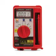 Triplett 2030
User Manual
Triplett 2030
User Manual
-
 Triplett 9055
User Manual
Triplett 9055
User Manual
-
 Triplett 9325
User Manual
Triplett 9325
User Manual
-
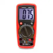 Triplett 9007A
User Manual
Triplett 9007A
User Manual
-
 Triplett 9007A-NIST
User Manual
Triplett 9007A-NIST
User Manual
-
 Triplett BBT858L
User Manual
Triplett BBT858L
User Manual
-
 Triplett CM1000
User Manual
Triplett CM1000
User Manual
-
 Triplett CM1000-NIST
User Manual
Triplett CM1000-NIST
User Manual
-
 Triplett CM1050
User Manual
Triplett CM1050
User Manual
-
 Triplett CM1050-NIST
User Manual
Triplett CM1050-NIST
User Manual
-
 Triplett CM1070
User Manual
Triplett CM1070
User Manual
-
 Triplett CM200
User Manual
Triplett CM200
User Manual
-
 Triplett CM200-NIST
User Manual
Triplett CM200-NIST
User Manual
-
 Triplett CM24
User Manual
Triplett CM24
User Manual
-
 Triplett CM400
User Manual
Triplett CM400
User Manual
-
 Triplett CM400-NIST
User Manual
Triplett CM400-NIST
User Manual
-
 Triplett CM450
User Manual
Triplett CM450
User Manual
-
 Triplett CM450-NIST
User Manual
Triplett CM450-NIST
User Manual
-
 Triplett CM600
User Manual
Triplett CM600
User Manual
-
Triplett CM600-NIST
User Manual