Triplett CM675IR - User Manual
Triplett CM675IR Multimeter – User Manual, read for free online in PDF format. We hope this helps you resolve any issues you may have. If you have further questions, please contact us through the contact form.


Table of Contents:
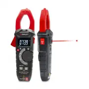
- Page 3 – AC/DC TRMS Clamp Meter with IR Thermometer; Page
- Page 4 – WARNINGS
- Page 9 – Set the function switch to the; VDC; Insert the black test lead into the; Input Jack and the red test lead into the; Positive; Input
- Page 16 – K Temp; Insert the Temperature Probe into the; and; Input Jack, making sure to observe the
- Page 17 – IR Temp; Button to switch on or off laser.; inch
- Page 18 – may randomly trip the sensor, this is normal operation.
- Page 19 – Battery Replacement
- Page 20 – Range; DC Current
- Page 21 – Frequency
"Loading the manual" means you need to wait until the file loads and becomes available for online reading. Some manuals are very large, and the time they take to appear depends on your internet speed.
Summary
3 AC/DC TRMS Clamp Meter with IR Thermometer Page 444556788910111213141516171819202022 Content 1.Safety.......................................................................................... 1-1.International Safety Symbols.................................................. 1-2.Safety Notes..........
4 AC/DC TRMS Clamp Meter with IR Thermometer 1.Safety 1-1.International Safety Symbols This symbol, adjacent to another symbol or terminal, indicates the user must refer to the manual for further information. This symbol, adjacent to a terminal, indicates that, under normal use, hazardous voltages m...
9 4-2.DC Voltage Measurement 1.Set the function switch to the VDC Position. 2.Insert the black test lead into the COM Input Jack and the red test lead into the Positive Input Jack.3.Connect the test leads in parallel to the circuit under test.4.Read the DC Voltage measurement on the LCD display. AC/...