Teka EH 60 4G AI AL TR CI NAT ANTHR. OS - Manuals
Teka EH 60 4G AI AL TR CI NAT ANTHR. OS Hob – User Manual in PDF format online.
Manuals:
User Manual Teka EH 60 4G AI AL TR CI NAT ANTHR. OS


Summary
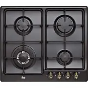
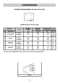
2 NG U - LPG 1 Ultra rapid gas burner of 15.0 MJ 11.9 MJ 2 Rapid gas burner of 12.0 MJ 10.8 MJ 3 Semirapid gas burner of 7.0 MJ 6.3 MJ 4 Auxiliary gas burner of 4.0 MJ 3.6 MJ 6 Enamelled steel pan support 2F right 7 Enamelled steel pan support 2F left 8 Burner n° 1 control knob 9 Burner n° 2 control...
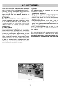
3 1) BURNERS A diagram is screen-printed above each knob on the front panel. This diagram indicates to which burner the knob in question corresponds. After having opened the gas mains or gas bottle tap, light the burners as described below: - manual ignition Push and turn the knob corresponding to t...
5 CLEANING IMPORTANT: always disconnect the appliance from the gas and electricity mains before carrying out any cleaning operation. 2) HOT PLATE Periodically wash the hot plate, the enamelled steel pan support, the enamelled burner caps “C” and the burner heads “T” (see fig. 6) with lukewarm soapy ...
Teka Hobs Manuals
-
 Teka CGW LUX 60 4G AI AL TR CI NAT
User Manual
Teka CGW LUX 60 4G AI AL TR CI NAT
User Manual
-
 Teka EM/30 2P (EXP)
User Manual
Teka EM/30 2P (EXP)
User Manual
-
 Teka IBC 64000
User Manual
Teka IBC 64000
User Manual
-
 Teka IZ 6420
User Manual
Teka IZ 6420
User Manual
-
 Teka IZ 6420 LONDON BRICK
User Manual
Teka IZ 6420 LONDON BRICK
User Manual
-
 Teka IZC 42300
User Manual
Teka IZC 42300
User Manual
-
 Teka IZC 64010
User Manual
Teka IZC 64010
User Manual
-
 Teka TM 620
User Manual
Teka TM 620
User Manual
-
Teka TM 620
Manual
-
 Teka VR 90 4G AI TR AL NAT
User Manual
Teka VR 90 4G AI TR AL NAT
User Manual
-
 Teka TT 600
Manual
Teka TT 600
Manual
-
 Teka TB 600
Manual
Teka TB 600
Manual
-
 Teka TR 620
Manual
Teka TR 620
Manual